How to Use Time of flight sensor: Examples, Pinouts, and Specs
Introduction
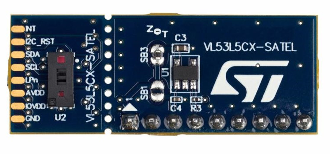
The VL53L5CX is a state-of-the-art Time of Flight (ToF) sensor manufactured by STM Electronics. It measures the distance to an object by calculating the time it takes for a light signal to travel to the object and return. This sensor is capable of multi-zone distance measurement, making it ideal for applications requiring precise depth sensing and spatial awareness.
Explore Projects Built with Time of flight sensor
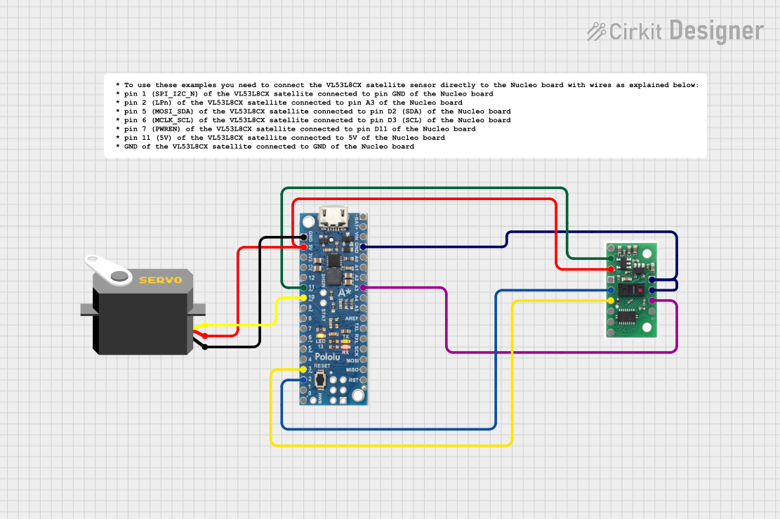

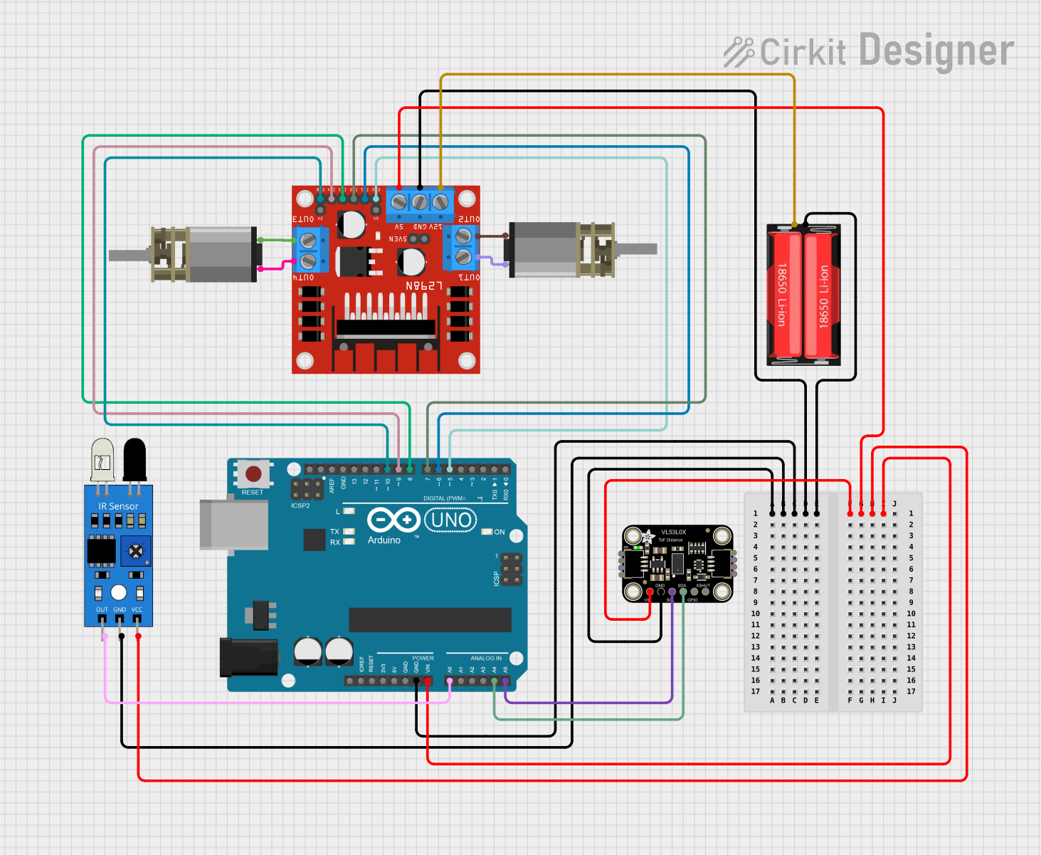
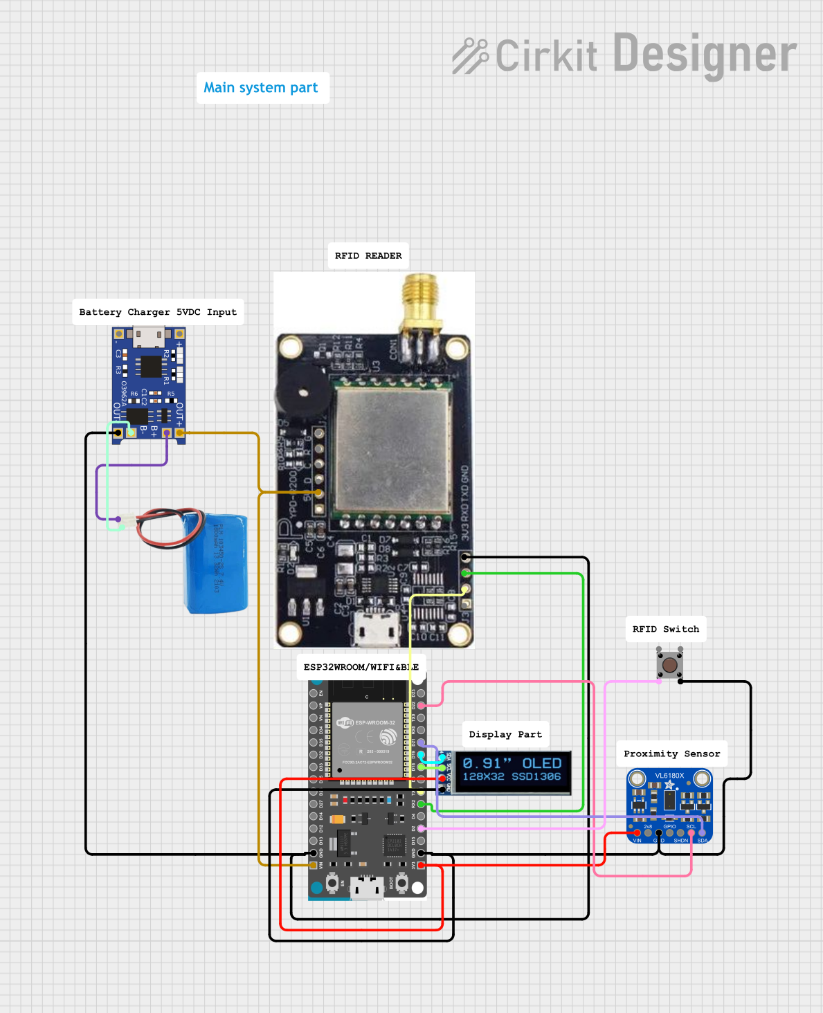
Explore Projects Built with Time of flight sensor
Common Applications and Use Cases
- Robotics and obstacle detection
- Gesture recognition
- Autonomous vehicles and drones
- Smart home devices (e.g., presence detection)
- Industrial automation and safety systems
- Augmented reality (AR) and virtual reality (VR) applications
Technical Specifications
The VL53L5CX is a highly versatile sensor with the following key specifications:
| Parameter | Value |
|---|---|
| Operating Voltage | 2.8 V (typical) |
| Communication Interface | I²C (up to 1 MHz) |
| Measurement Range | 0.1 m to 4 m (depending on target reflectance and environmental factors) |
| Field of View (FoV) | 45° x 45° |
| Multi-Zone Capability | Up to 64 zones (8x8 grid) |
| Measurement Accuracy | ±1% (typical, under standard conditions) |
| Power Consumption | 5.4 mW (typical in active mode) |
| Operating Temperature Range | -20°C to +85°C |
| Package Dimensions | 6.4 mm x 3.0 mm x 1.5 mm |
Pin Configuration and Descriptions
The VL53L5CX has the following pinout:
| Pin Name | Pin Number | Description |
|---|---|---|
| GND | 1 | Ground connection |
| VIN | 2 | Power supply input (2.8 V typical) |
| SDA | 3 | I²C data line |
| SCL | 4 | I²C clock line |
| GPIO1 | 5 | General-purpose I/O pin (can be used for interrupt signaling) |
| GPIO0 | 6 | General-purpose I/O pin |
| AVDD | 7 | Analog power supply input |
| AVSS | 8 | Analog ground |
Usage Instructions
How to Use the VL53L5CX in a Circuit
- Power Supply: Connect the VIN pin to a 2.8 V power source and the GND pin to ground.
- I²C Communication: Connect the SDA and SCL pins to the corresponding I²C pins on your microcontroller. Use pull-up resistors (typically 4.7 kΩ) on both lines.
- Interrupts (Optional): If needed, connect GPIO1 to a microcontroller pin to handle interrupts for events like measurement completion.
- Bypass Capacitors: Place a 100 nF capacitor close to the VIN and GND pins to stabilize the power supply.
Important Considerations and Best Practices
- Ambient Light: Avoid placing the sensor in direct sunlight or near strong light sources, as this can affect measurement accuracy.
- Reflective Surfaces: Highly reflective or transparent surfaces may cause inaccurate readings. Test the sensor in your specific environment.
- I²C Address: The default I²C address of the VL53L5CX is
0x52. Ensure no other devices on the I²C bus share this address. - Mounting: Ensure the sensor's field of view is unobstructed for optimal performance.
Example Code for Arduino UNO
Below is an example of how to interface the VL53L5CX with an Arduino UNO using the I²C protocol:
#include <Wire.h>
#include <VL53L5CX.h> // Include the VL53L5CX library

VL53L5CX sensor; // Create a sensor object

void setup() {
  Serial.begin(9600); // Initialize serial communication
  Wire.begin();       // Initialize I²C communication

  // Initialize the VL53L5CX sensor
  if (!sensor.begin()) {
    Serial.println("Failed to initialize VL53L5CX sensor!");
    while (1); // Halt execution if initialization fails
  }

  Serial.println("VL53L5CX initialized successfully!");
}

void loop() {
  uint16_t distance; // Variable to store measured distance

  // Perform a distance measurement
  if (sensor.getDistance(&distance)) {
    Serial.print("Distance: ");
    Serial.print(distance);
    Serial.println(" mm");
  } else {
    Serial.println("Failed to read distance!");
  }

  delay(500); // Wait 500 ms before the next measurement
}
Notes:
- Install the VL53L5CX library in your Arduino IDE before running the code.
- Adjust the
delay()value in the loop to control the measurement frequency.
Troubleshooting and FAQs
Common Issues and Solutions
Sensor Not Detected on I²C Bus
- Ensure the SDA and SCL lines are correctly connected to the microcontroller.
- Verify that pull-up resistors are present on the I²C lines.
- Check the sensor's power supply voltage (2.8 V typical).
Inaccurate Distance Measurements
- Avoid using the sensor in environments with excessive ambient light.
- Ensure the target object is within the sensor's measurement range (0.1 m to 4 m).
- Clean the sensor's lens to remove dust or smudges.
Intermittent Readings
- Verify that the power supply is stable and free of noise.
- Check for loose connections in the circuit.
FAQs
Q: Can the VL53L5CX measure multiple distances simultaneously?
A: Yes, the VL53L5CX supports multi-zone measurements, allowing it to measure distances in up to 64 zones (8x8 grid).
Q: What is the maximum I²C clock speed supported by the VL53L5CX?
A: The VL53L5CX supports I²C clock speeds of up to 1 MHz.
Q: Can the sensor operate in outdoor environments?
A: While the VL53L5CX can operate outdoors, its performance may be affected by direct sunlight or extreme temperatures. Use appropriate shielding or enclosures for outdoor applications.
Q: Is the VL53L5CX compatible with 5 V microcontrollers?
A: The VL53L5CX operates at 2.8 V. Use a level shifter to interface it with 5 V microcontrollers.
By following this documentation, users can effectively integrate the VL53L5CX Time of Flight sensor into their projects and troubleshoot common issues.