How to Use ESP 32 DEVKIT V4: Examples, Pinouts, and Specs
Introduction
The ESP32 DEVKIT V4 is a versatile development board built around the powerful ESP32 chip. It features integrated Wi-Fi and Bluetooth capabilities, making it an excellent choice for Internet of Things (IoT) applications, wireless communication projects, and rapid prototyping. With its dual-core processor, low power consumption, and extensive GPIO options, the ESP32 DEVKIT V4 is suitable for a wide range of applications, from smart home devices to industrial automation.
Explore Projects Built with ESP 32 DEVKIT V4


Explore Projects Built with ESP 32 DEVKIT V4
Common Applications and Use Cases
- IoT devices and smart home automation
- Wireless sensor networks
- Bluetooth-enabled applications
- Robotics and automation systems
- Prototyping and educational projects
Technical Specifications
The ESP32 DEVKIT V4 is designed to provide robust performance and flexibility. Below are its key technical specifications:
| Specification | Details |
|---|---|
| Microcontroller | ESP32-D0WDQ6 chip with dual-core Xtensa® 32-bit LX6 microprocessor |
| Clock Speed | Up to 240 MHz |
| Flash Memory | 4 MB (varies by model) |
| SRAM | 520 KB |
| Wireless Connectivity | Wi-Fi 802.11 b/g/n, Bluetooth v4.2 + BLE |
| Operating Voltage | 3.3V |
| Input Voltage (VIN) | 5V (via USB or external power supply) |
| GPIO Pins | 30 (varies slightly by manufacturer) |
| ADC Channels | 18 (12-bit resolution) |
| DAC Channels | 2 |
| Communication Interfaces | UART, SPI, I2C, I2S, CAN, PWM |
| Power Consumption | Ultra-low power consumption in deep sleep mode (as low as 10 µA) |
| Dimensions | Approx. 54 mm x 27 mm |
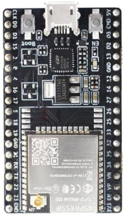
Pin Configuration and Descriptions
The ESP32 DEVKIT V4 features a 30-pin layout. Below is a table describing the key pins:
| Pin | Name | Description |
|---|---|---|
| 1 | EN | Reset pin. Pulling this pin low resets the board. |
| 2 | IO0 | GPIO0. Used for boot mode selection during programming. |
| 3-16 | GPIO Pins | General-purpose input/output pins. Can be configured for various functions. |
| 17 | VIN | Input voltage (5V). Powers the board when not connected via USB. |
| 18 | 3V3 | 3.3V output. Can be used to power external components. |
| 19 | GND | Ground pin. |
| 20-21 | TXD, RXD | UART communication pins (TX and RX). |
| 22-23 | SDA, SCL | I2C communication pins (data and clock). |
| 24-25 | ADC1, ADC2 | Analog-to-digital converter pins. |
| 26-27 | DAC1, DAC2 | Digital-to-analog converter pins. |
| 28 | BOOT | Boot mode selection button. |
| 29-30 | SPI Pins | SPI communication pins (MOSI, MISO, SCK, CS). |
Usage Instructions
How to Use the ESP32 DEVKIT V4 in a Circuit
Powering the Board:
- Connect the board to your computer via a micro-USB cable for power and programming.
- Alternatively, supply 5V to the VIN pin and connect GND to the ground of your power source.
Programming the Board:
- Install the Arduino IDE and add the ESP32 board support package.
- Select "ESP32 DEVKIT V4" from the Tools > Board menu.
- Connect the board to your computer and select the appropriate COM port.
Connecting Peripherals:
- Use the GPIO pins to connect sensors, actuators, or other peripherals.
- Ensure that the voltage levels of connected devices are compatible with the ESP32 (3.3V logic).
Uploading Code:
- Write your code in the Arduino IDE or another compatible environment.
- Press the "Upload" button to flash the code to the ESP32.
- If the upload fails, press and hold the BOOT button while uploading.
Example Code: Blinking an LED
The following example demonstrates how to blink an LED connected to GPIO2:
// Define the GPIO pin where the LED is connected
const int ledPin = 2;

void setup() {
  // Set the LED pin as an output
  pinMode(ledPin, OUTPUT);
}

void loop() {
  // Turn the LED on
  digitalWrite(ledPin, HIGH);
  delay(1000); // Wait for 1 second

  // Turn the LED off
  digitalWrite(ledPin, LOW);
  delay(1000); // Wait for 1 second
}
Important Considerations and Best Practices
- Voltage Levels: Ensure all connected peripherals operate at 3.3V logic levels to avoid damaging the ESP32.
- Deep Sleep Mode: Use deep sleep mode to conserve power in battery-powered applications.
- Boot Mode: If the board fails to upload code, ensure GPIO0 is pulled low during the upload process.
- Wi-Fi and Bluetooth: Avoid placing the board near metal objects or enclosures that may interfere with wireless signals.
Troubleshooting and FAQs
Common Issues and Solutions
Problem: The board is not detected by the computer.
Solution:- Ensure the USB cable is functional and supports data transfer.
- Install the correct USB-to-serial driver for your operating system.
Problem: Code upload fails with a timeout error.
Solution:- Press and hold the BOOT button while uploading the code.
- Check that the correct COM port and board are selected in the Arduino IDE.
Problem: Wi-Fi connection is unstable.
Solution:- Ensure the board is within range of the Wi-Fi router.
- Check for interference from other devices operating on the same frequency.
Problem: GPIO pins are not functioning as expected.
Solution:- Verify the pin configuration in your code.
- Check for conflicting pin assignments (e.g., some pins are reserved for specific functions).
FAQs
Can I power the ESP32 DEVKIT V4 with a battery?
Yes, you can use a 3.7V LiPo battery connected to the VIN and GND pins. Ensure the battery voltage is regulated.What is the maximum current output of the 3.3V pin?
The 3.3V pin can supply up to 500 mA, depending on the input power source.Can I use the ESP32 DEVKIT V4 with MicroPython?
Yes, the ESP32 is compatible with MicroPython. You can flash the MicroPython firmware to the board and use it for development.How do I reset the board?
Press the EN (reset) button to restart the ESP32.
This documentation provides a comprehensive guide to using the ESP32 DEVKIT V4 effectively. For further assistance, refer to the official ESP32 documentation or community forums.