How to Use ToF / Laser moodul: Examples, Pinouts, and Specs
Introduction
The VL53L0X, manufactured by Okystar, is a Time-of-Flight (ToF) laser module designed for precise distance measurement. It operates by emitting a laser pulse and calculating the time it takes for the reflected light to return to the sensor. This compact and efficient module is ideal for applications requiring accurate distance sensing, such as robotics, autonomous vehicles, gesture recognition, and 3D mapping.
Explore Projects Built with ToF / Laser moodul
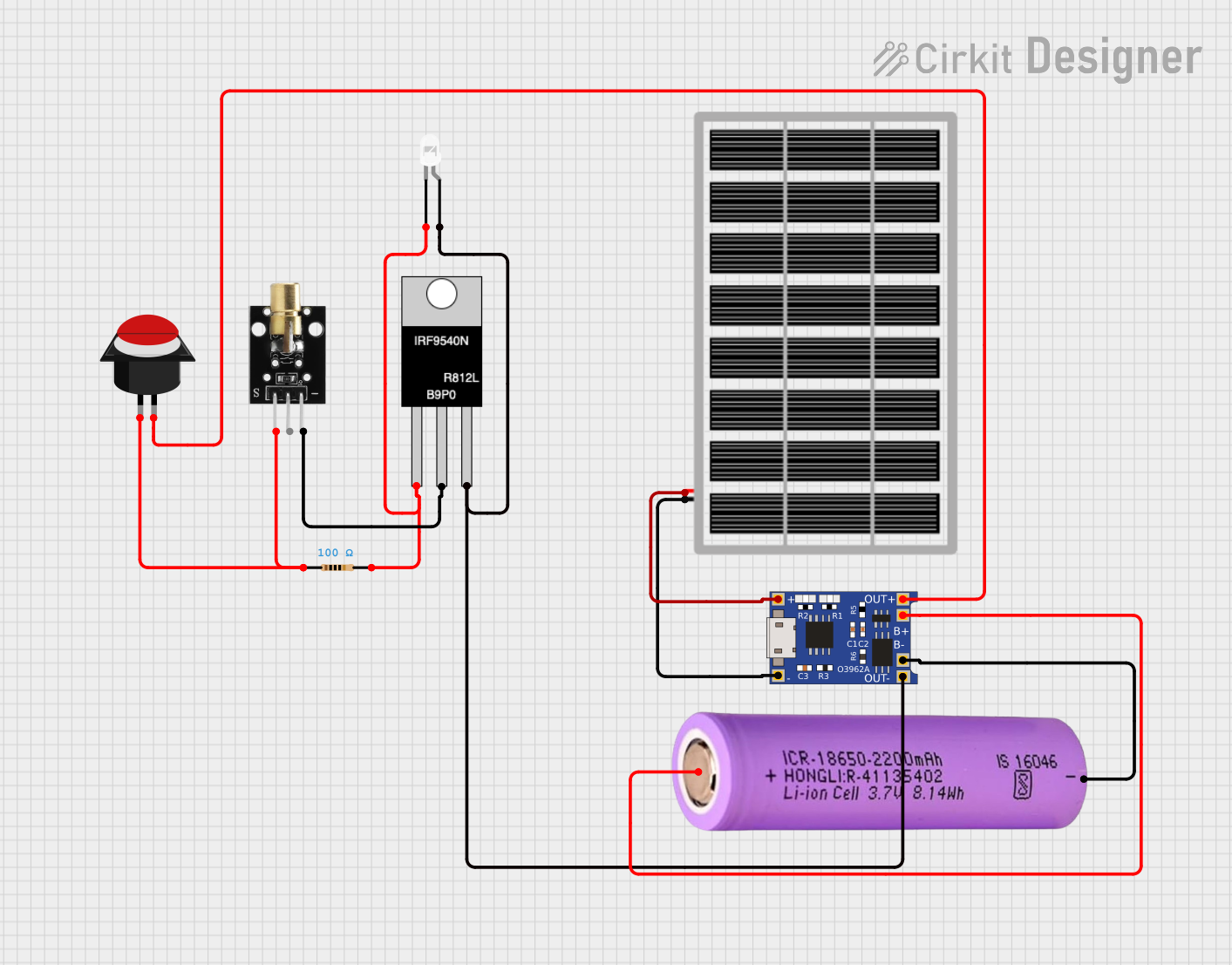
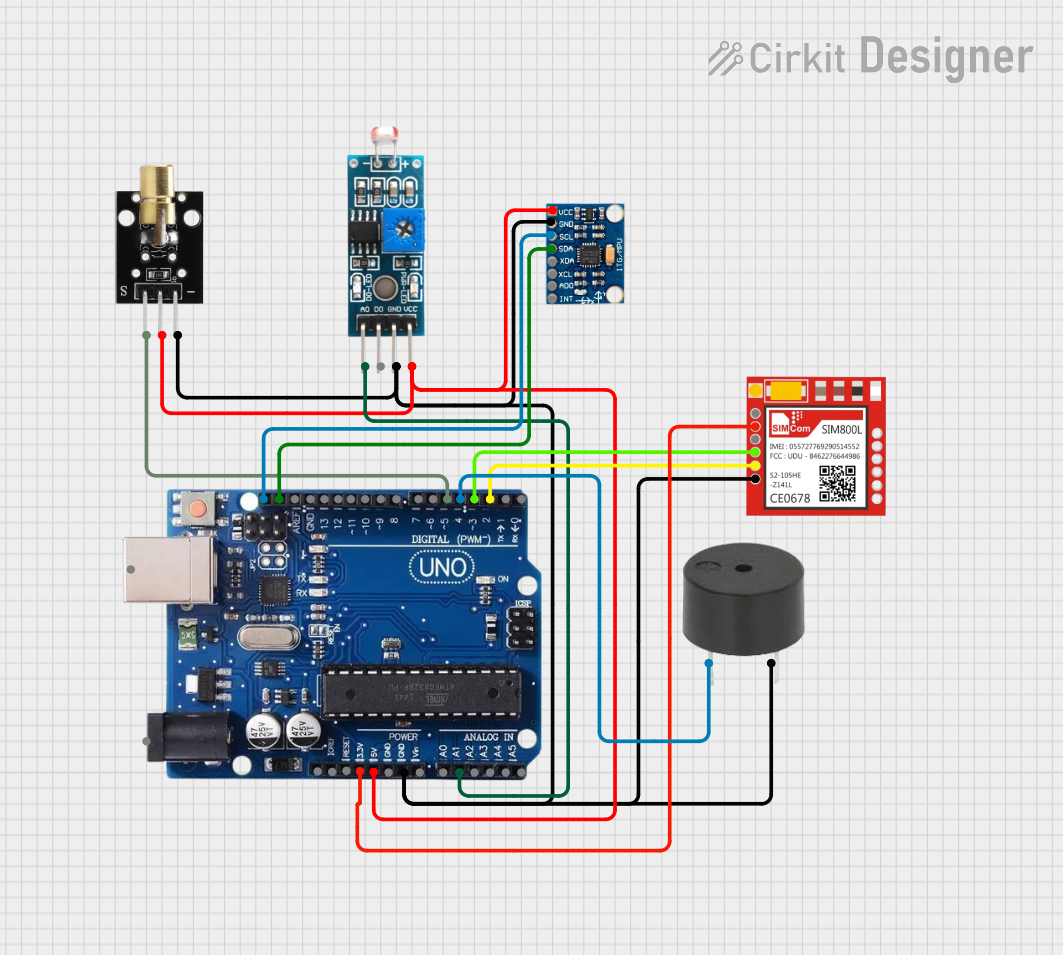
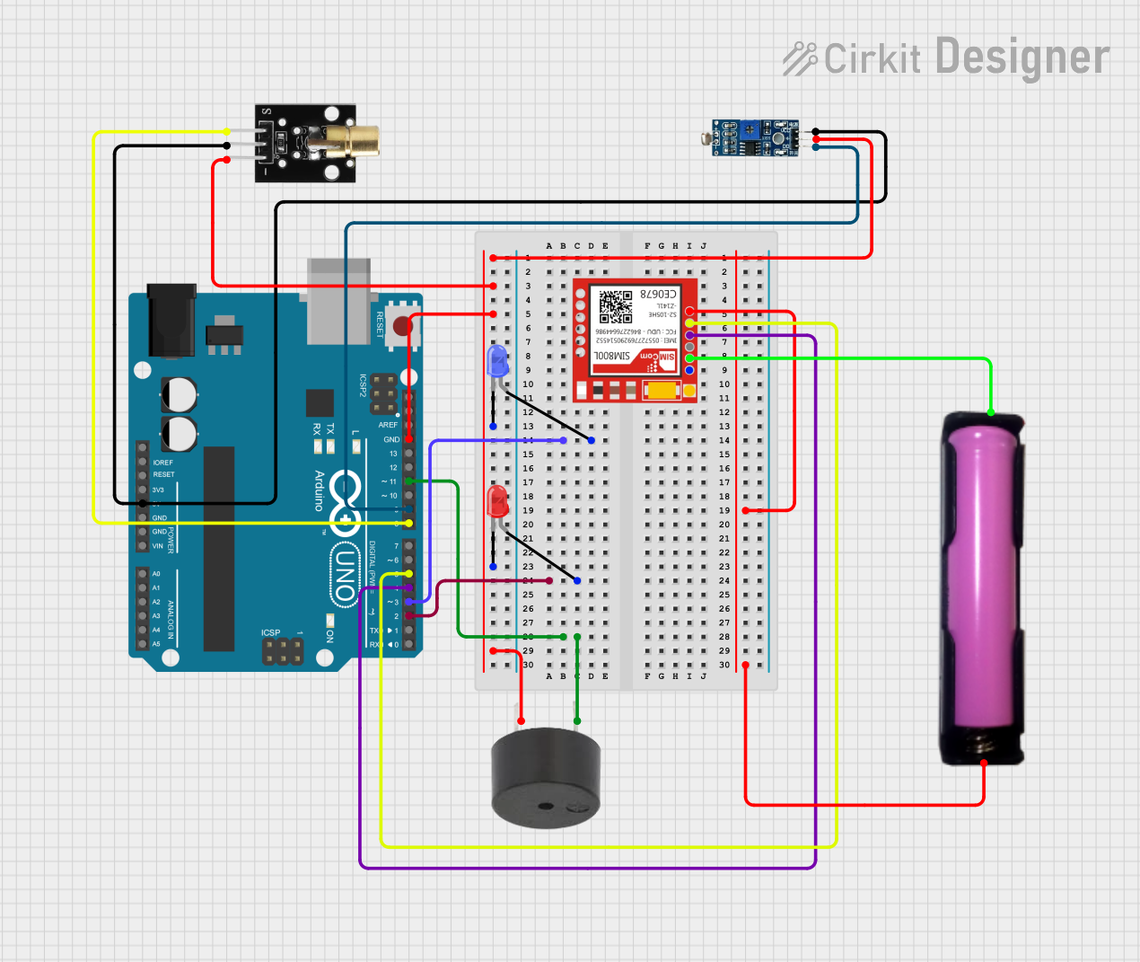
Explore Projects Built with ToF / Laser moodul
Common Applications
- Obstacle detection in robotics
- Autonomous vehicle navigation
- Gesture-based user interfaces
- 3D scanning and mapping
- Proximity sensing in IoT devices
Technical Specifications
The VL53L0X module offers high performance in a small form factor. Below are its key technical details:
| Parameter | Value |
|---|---|
| Operating Voltage | 2.6V to 3.5V |
| Communication Interface | I²C |
| Measurement Range | Up to 2 meters |
| Accuracy | ±3% |
| Operating Temperature | -20°C to +70°C |
| Laser Wavelength | 940 nm (infrared, invisible) |
| Power Consumption | 20 mW (typical) |
| Dimensions | 4.4 mm x 2.4 mm x 1.0 mm |
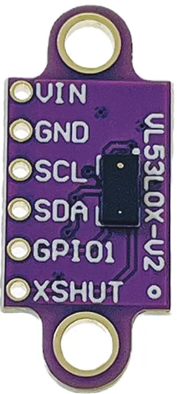
Pin Configuration
The VL53L0X module has the following pinout:
| Pin Name | Description |
|---|---|
| VIN | Power supply input (2.6V to 3.5V) |
| GND | Ground |
| SDA | I²C data line |
| SCL | I²C clock line |
| XSHUT | Shutdown pin (active low) |
| GPIO1 | Interrupt output (optional) |
Usage Instructions
Connecting the VL53L0X to an Arduino UNO
To use the VL53L0X module with an Arduino UNO, follow these steps:
Wiring: Connect the module to the Arduino as shown below:
VINto Arduino5V(use a level shifter if needed for 3.3V logic)GNDto ArduinoGNDSDAto ArduinoA4(I²C data line)SCLto ArduinoA5(I²C clock line)XSHUTandGPIO1can be left unconnected for basic operation.
Install Libraries: Download and install the Adafruit VL53L0X library from the Arduino Library Manager.
Upload Code: Use the following example code to read distance measurements:
#include <Wire.h>
#include <Adafruit_VL53L0X.h>

// Create an instance of the VL53L0X sensor
Adafruit_VL53L0X lox = Adafruit_VL53L0X();

void setup() {
  Serial.begin(9600); // Initialize serial communication
  while (!Serial) {
    delay(10); // Wait for the serial monitor to open
  }

  Serial.println("VL53L0X ToF Sensor Test");

  // Initialize the sensor
  if (!lox.begin()) {
    Serial.println("Failed to find VL53L0X sensor!");
    while (1) {
      delay(10); // Halt execution if sensor initialization fails
    }
  }
}

void loop() {
  VL53L0X_RangingMeasurementData_t measure;

  // Perform a distance measurement
  lox.rangingTest(&measure, false);

  // Check if the measurement is valid
  if (measure.RangeStatus != 4) { // 4 indicates an out-of-range error
    Serial.print("Distance (mm): ");
    Serial.println(measure.RangeMilliMeter);
  } else {
    Serial.println("Out of range");
  }

  delay(100); // Wait before the next measurement
}
Important Considerations
- Power Supply: Ensure the module is powered within its operating voltage range (2.6V to 3.5V). If using a 5V microcontroller, use a level shifter for I²C lines.
- Ambient Light: The sensor may be affected by strong ambient light. Use it in controlled lighting conditions for best results.
- Reflective Surfaces: Highly reflective or transparent surfaces may cause inaccurate readings.
Troubleshooting and FAQs
Common Issues
Sensor Not Detected:
- Ensure proper wiring of the I²C lines (
SDAandSCL). - Verify that the sensor is powered correctly.
- Check the I²C address (default is
0x29).
- Ensure proper wiring of the I²C lines (
Inaccurate Measurements:
- Avoid using the sensor in direct sunlight or near strong infrared sources.
- Ensure the target surface is not too reflective or transparent.
Out-of-Range Errors:
- Ensure the target is within the sensor's measurement range (up to 2 meters).
- Check for obstructions between the sensor and the target.
FAQs
Q: Can the VL53L0X measure distances beyond 2 meters?
A: No, the maximum range of the VL53L0X is approximately 2 meters under optimal conditions.
Q: Is the laser emitted by the VL53L0X safe for human eyes?
A: Yes, the VL53L0X uses a Class 1 laser, which is safe for human eyes under normal operating conditions.
Q: Can I use multiple VL53L0X sensors on the same I²C bus?
A: Yes, but you must change the I²C address of each sensor using the XSHUT pin to avoid address conflicts.
By following this documentation, you can effectively integrate the VL53L0X ToF laser module into your projects for accurate and reliable distance measurements.