How to Use led driver arus connstan: Examples, Pinouts, and Specs
Introduction
A constant current LED driver is an electronic component designed to regulate the current flowing through LED lights. Unlike constant voltage drivers, this component ensures a steady current supply, which is critical for maintaining consistent brightness and protecting LEDs from overcurrent damage.
Explore Projects Built with led driver arus connstan


Explore Projects Built with led driver arus connstan
Common Applications and Use Cases
- LED lighting systems in residential, commercial, and industrial environments
- Backlighting for displays and signage
- Automotive LED lighting
- Architectural lighting installations
- LED strips and arrays requiring precise current control
Technical Specifications
Below are the key technical details for a typical constant current LED driver:
| Parameter | Value |
|---|---|
| Input Voltage Range | 6V to 36V DC |
| Output Current Range | 300mA to 1A (model-dependent) |
| Output Voltage Range | 2V to 34V DC |
| Efficiency | Up to 95% |
| Dimming Control | PWM or Analog (0-10V) |
| Operating Temperature | -40°C to +85°C |
| Protection Features | Overcurrent, Overvoltage, Thermal Shutdown |
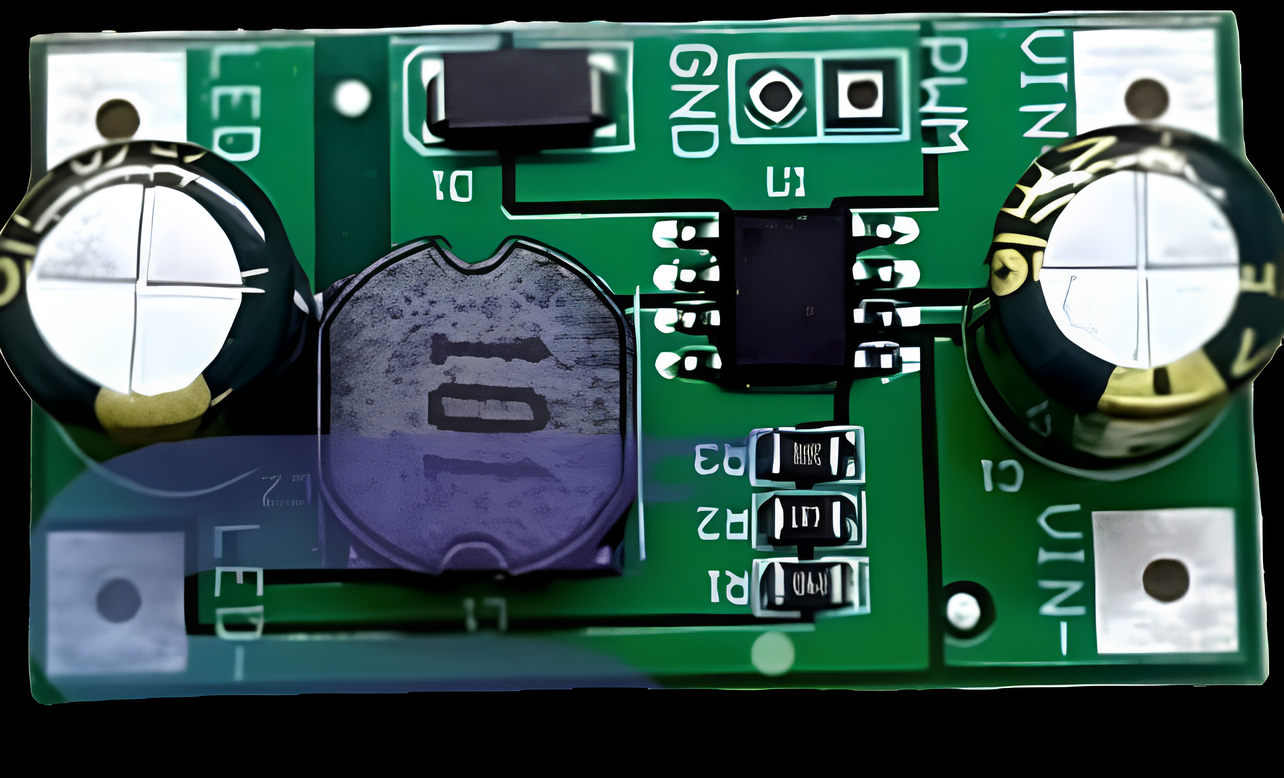
Pin Configuration and Descriptions
The pinout for a typical constant current LED driver IC is as follows:
| Pin Name | Pin Number | Description |
|---|---|---|
| VIN | 1 | Input voltage pin. Connect to the DC power supply. |
| GND | 2 | Ground pin. Connect to the ground of the circuit. |
| LED+ | 3 | Positive output terminal. Connect to the anode (+) of the LED. |
| LED- | 4 | Negative output terminal. Connect to the cathode (-) of the LED. |
| DIM | 5 | Dimming control pin. Accepts PWM or analog signals for brightness adjustment. |
| NC | 6 | No connection. Leave this pin unconnected or follow the datasheet guidelines. |
Usage Instructions
How to Use the Component in a Circuit
- Power Supply: Connect a DC power supply to the
VINandGNDpins. Ensure the input voltage is within the specified range of the driver. - LED Connection: Connect the LED(s) to the
LED+andLED-pins. Ensure the total forward voltage of the LED(s) is within the driver's output voltage range. - Dimming Control (Optional): If dimming is required, connect a PWM or analog signal to the
DIMpin. For example:- Use a PWM signal from a microcontroller (e.g., Arduino) for digital dimming.
- Use a potentiometer or 0-10V analog signal for manual dimming.
- Thermal Management: Ensure proper heat dissipation by mounting the driver on a heatsink or providing adequate ventilation.
Important Considerations and Best Practices
- Current Selection: Choose a driver with a current rating that matches the LED's requirements. Exceeding the LED's current rating can cause overheating or damage.
- Voltage Compatibility: Ensure the input voltage is within the driver's specified range and that the output voltage matches the LED's forward voltage.
- Dimming Signal: When using PWM dimming, ensure the frequency is within the driver's supported range (typically 100Hz to 1kHz).
- Wiring: Use appropriate wire gauges to handle the current without excessive resistance or heat generation.
- Protection: Verify that the driver includes protection features such as overcurrent and thermal shutdown to safeguard the LEDs and the driver itself.
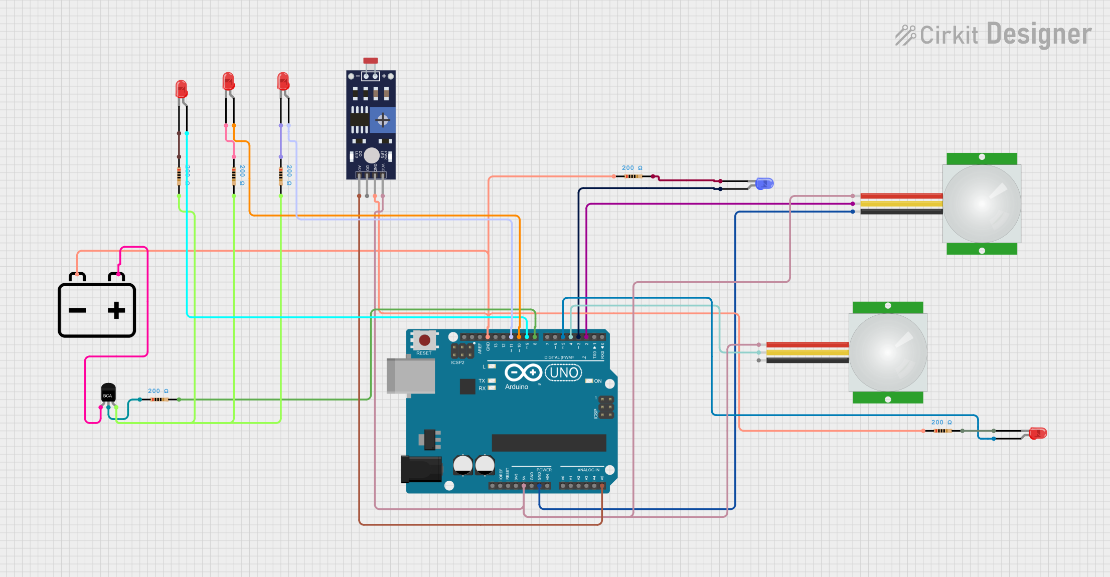
Example: Connecting to an Arduino UNO
Below is an example of using an Arduino UNO to control the brightness of an LED via PWM dimming:
// Define the PWM pin connected to the DIM pin of the LED driver
const int dimPin = 9;

void setup() {
  // Set the dimPin as an output
  pinMode(dimPin, OUTPUT);
}

void loop() {
  // Gradually increase brightness
  for (int brightness = 0; brightness <= 255; brightness++) {
    analogWrite(dimPin, brightness); // Write PWM signal to DIM pin
    delay(10); // Small delay for smooth transition
  }

  // Gradually decrease brightness
  for (int brightness = 255; brightness >= 0; brightness--) {
    analogWrite(dimPin, brightness); // Write PWM signal to DIM pin
    delay(10); // Small delay for smooth transition
  }
}
Troubleshooting and FAQs
Common Issues and Solutions
| Issue | Possible Cause | Solution |
|---|---|---|
| LED does not light up | Incorrect wiring or insufficient input voltage | Verify connections and ensure the input voltage is within the specified range. |
| LED flickers | Incompatible PWM frequency or unstable power supply | Use a stable power source and ensure the PWM frequency is within the supported range. |
| LED is too dim or too bright | Incorrect current setting or dimming signal | Check the driver's current rating and verify the dimming signal. |
| Driver overheats | Insufficient cooling or excessive load | Improve heat dissipation or reduce the number of LEDs connected. |
| Dimming does not work | Incorrect connection to DIM pin | Verify the PWM or analog signal is properly connected to the DIM pin. |
FAQs
Can I use this driver with multiple LEDs?
- Yes, as long as the total forward voltage of the LEDs is within the driver's output voltage range and the current rating matches the LEDs' requirements.
What happens if I exceed the driver's input voltage?
- Exceeding the input voltage can damage the driver. Always use a power supply within the specified range.
Can I use this driver with a constant voltage power supply?
- Yes, as long as the power supply's voltage is within the driver's input range. The driver will regulate the current to the LEDs.
Is it safe to operate the driver without a heatsink?
- It depends on the power dissipation. For high-power applications, a heatsink or proper ventilation is recommended to prevent overheating.
By following this documentation, you can effectively use a constant current LED driver to power and control your LED lighting systems.