How to Use OpenSegment Serial Display - 20mm (RED): Examples, Pinouts, and Specs
Introduction
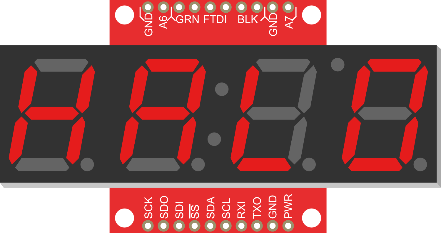
The OpenSegment Serial Display is a versatile and bright single-digit 7-segment LED display designed for numeric output in electronics projects. Its 20mm size and vibrant red color make it highly visible, and it is capable of being controlled through serial communication, making it an excellent choice for applications such as counters, timers, and readouts in various devices.
Explore Projects Built with OpenSegment Serial Display - 20mm (RED)

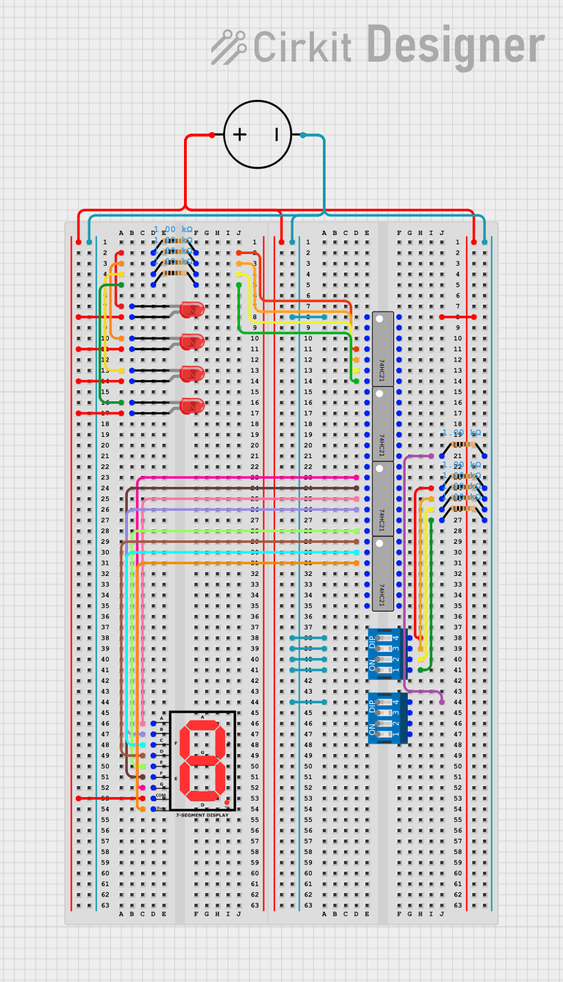
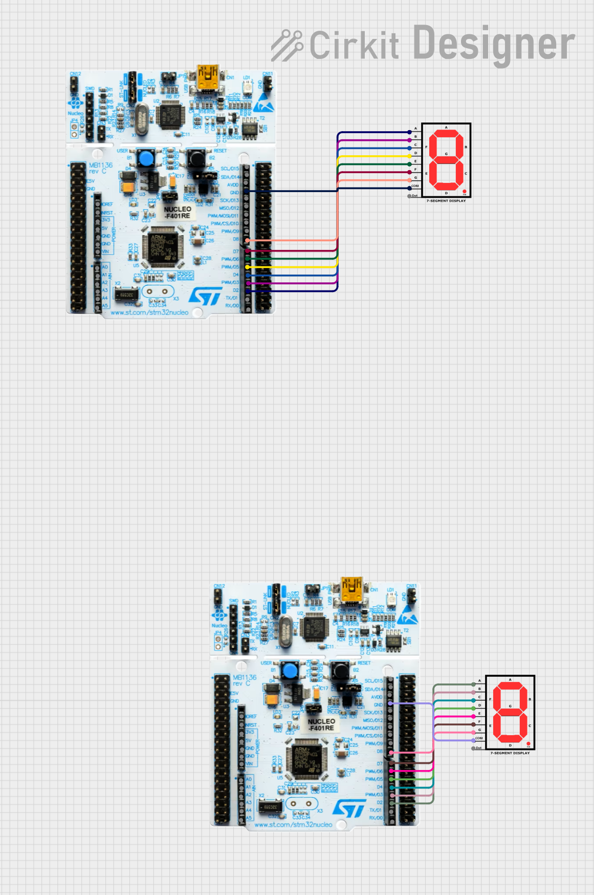

Explore Projects Built with OpenSegment Serial Display - 20mm (RED)
Common Applications and Use Cases
- Digital clocks and timers
- Counter displays for events or devices
- Temperature or other sensor value readouts
- Scoreboards for games or sports
- User interface for electronic devices
Technical Specifications
Key Technical Details
- Display Color: Red
- Character Height: 20mm
- Operating Voltage: 3.3V to 5V
- Maximum Current: 80mA (typical brightness)
- Communication: Serial (TTL compatible)
- Baud Rate: 9600 (default)
Pin Configuration and Descriptions
| Pin Number | Name | Description |
|---|---|---|
| 1 | VCC | Power supply (3.3V to 5V) |
| 2 | GND | Ground connection |
| 3 | RX | Serial receive pin |
| 4 | TX | Serial transmit pin (not used) |
Usage Instructions
How to Use the Component in a Circuit
- Power Connection: Connect the VCC pin to a 3.3V or 5V power supply and the GND pin to the ground.
- Serial Connection: Connect the RX pin to the TX pin of your microcontroller (e.g., Arduino UNO).
- Programming: Use serial commands to control the display (see example code below).
Important Considerations and Best Practices
- Ensure that the power supply voltage matches the operating voltage of the display.
- Limit the current to avoid damaging the display—use appropriate resistors if necessary.
- When using with a microcontroller, ensure that the serial communication settings (baud rate, data bits, etc.) match the display's requirements.
- Avoid exposing the display to moisture or extreme temperatures.
Example Code for Arduino UNO
#include <SoftwareSerial.h>

// RX pin is not used in this example, hence we set it to -1.
SoftwareSerial openSegmentSerial(-1, 2); // RX, TX

void setup() {
  // Start serial communication with the display at 9600 baud rate.
  openSegmentSerial.begin(9600);
}

void loop() {
  // Send a numeric value to the display.
  openSegmentSerial.print(5);
  delay(1000); // Wait for 1 second.

  // Clear the display.
  openSegmentSerial.write(0x76); // Clear command for OpenSegment.
  delay(1000); // Wait for 1 second.
}
Troubleshooting and FAQs
Common Issues Users Might Face
- Display Not Lighting Up: Check the power connections and ensure that the voltage is within the specified range. Also, verify that the current is not exceeding the maximum rating.
- Garbled or Incorrect Output: Ensure that the baud rate of the microcontroller's serial communication matches the display's default baud rate. Check for correct serial connections.
- Display Flickering: This can be caused by insufficient power supply or loose connections. Ensure that all connections are secure and the power supply is stable.
Solutions and Tips for Troubleshooting
- Double-check wiring, especially the VCC and GND connections.
- Use a multimeter to verify the voltage at the display's power pins.
- If using long wires, consider using a lower resistance wire or placing the display closer to the microcontroller to minimize voltage drop.
- For communication issues, use a logic analyzer or oscilloscope to check the serial data being transmitted to the display.
FAQs
Q: Can I chain multiple displays together? A: This particular model is a single-digit display and does not support chaining. You would need to control multiple displays individually.
Q: What is the default baud rate for the display? A: The default baud rate is 9600.
Q: Can I use this display with a 3.3V system? A: Yes, the display operates between 3.3V and 5V, making it compatible with both 3.3V and 5V systems.
Q: How do I change the baud rate of the display? A: The baud rate can typically be changed through specific serial commands or configuration settings. Refer to the manufacturer's datasheet for detailed instructions.
Q: Is it possible to display letters as well as numbers? A: The 7-segment display is primarily designed for numbers, but some letters can be approximated. The exact capability will depend on the controller used with the display.