How to Use 4 wire PWM fan: Examples, Pinouts, and Specs
Introduction
A 4-wire PWM fan is a type of cooling fan designed for precise speed control and efficient thermal management. Unlike traditional 2-wire or 3-wire fans, the 4-wire PWM fan incorporates a dedicated PWM control signal, allowing the fan speed to be dynamically adjusted based on system requirements. This feature makes it ideal for applications where noise reduction, energy efficiency, and temperature regulation are critical.
Explore Projects Built with 4 wire PWM fan
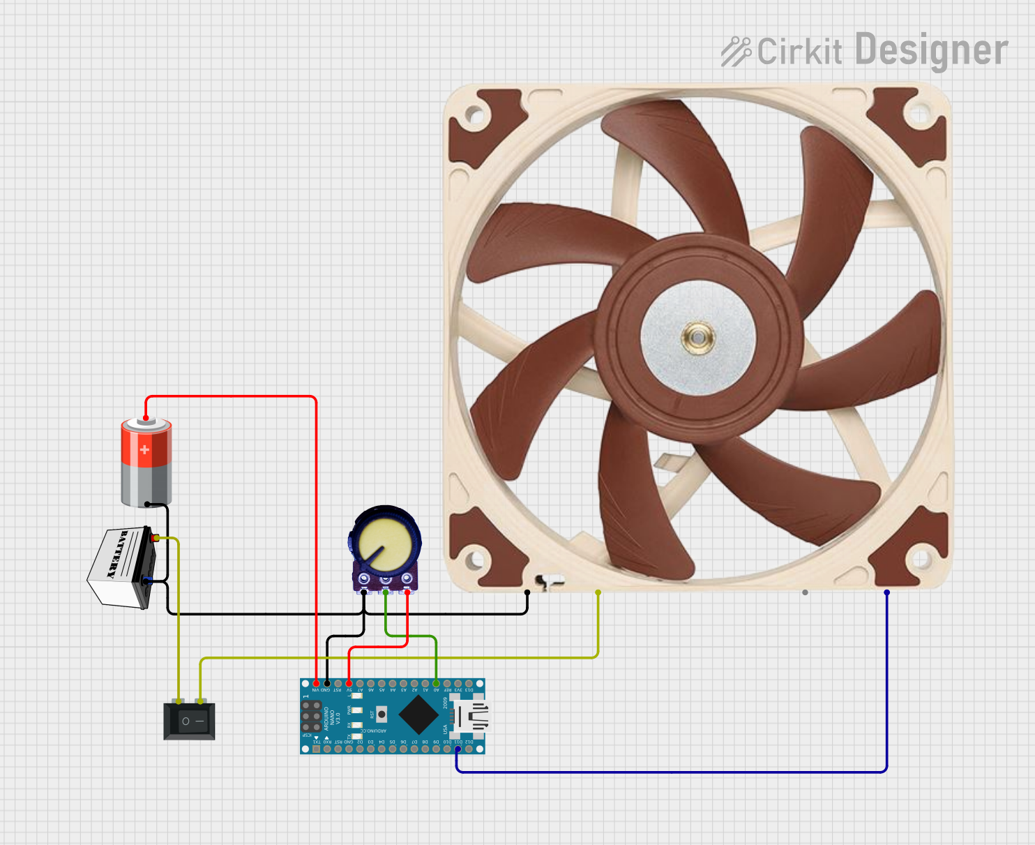
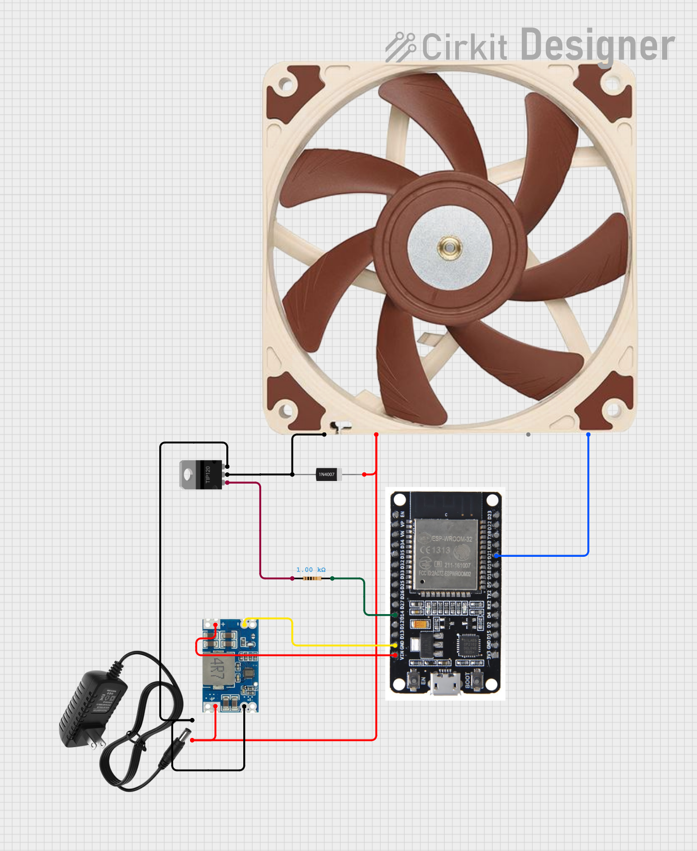

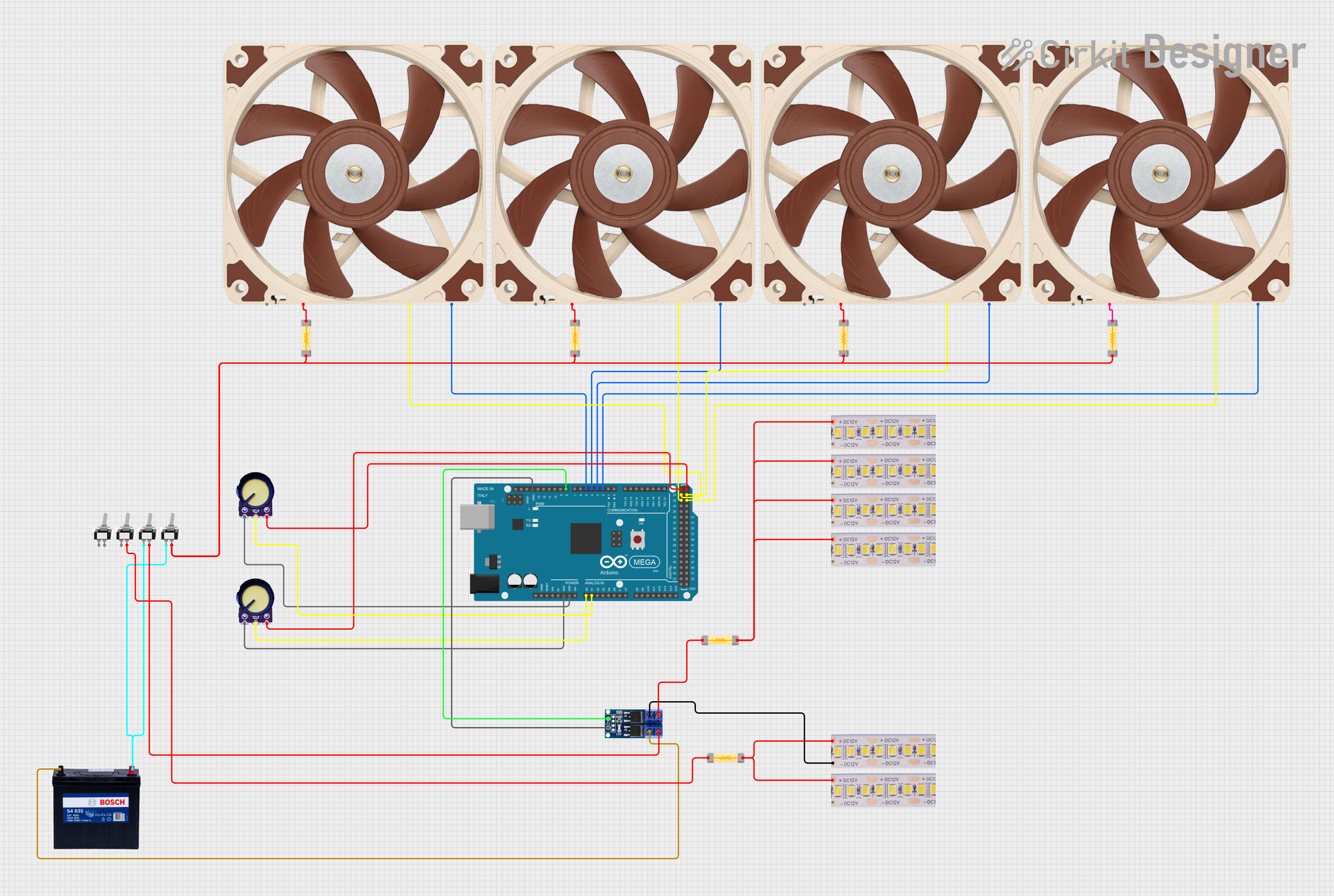
Explore Projects Built with 4 wire PWM fan
Common Applications
- Computer CPU and GPU cooling
- Server and data center cooling systems
- Industrial equipment requiring thermal management
- Consumer electronics, such as gaming consoles
- Embedded systems with temperature-sensitive components
Technical Specifications
Key Technical Details
| Parameter | Value/Range |
|---|---|
| Operating Voltage | Typically 12V DC (varies by model) |
| Current Rating | 0.1A to 1A (depending on size/power) |
| PWM Signal Voltage | 3.3V or 5V logic level |
| PWM Frequency Range | 20 kHz to 25 kHz (standard) |
| Speed Control Duty Cycle | 0% (off) to 100% (full speed) |
| Tachometer Signal Output | Open-drain or open-collector |
| Connector Type | 4-pin Molex KK or similar |
Pin Configuration and Descriptions
| Pin Number | Wire Color (Typical) | Function | Description |
|---|---|---|---|
| 1 | Black | Ground (GND) | Provides the return path for the current. Connect to the system ground. |
| 2 | Yellow | Power (VCC) | Supplies operating voltage to the fan. Typically 12V DC. |
| 3 | Green | Tachometer (TACH) | Outputs a signal proportional to fan speed. Used for speed monitoring. |
| 4 | Blue | PWM Control | Accepts a PWM signal to control fan speed. Operates at 3.3V or 5V logic. |
Usage Instructions
How to Use the 4-Wire PWM Fan in a Circuit
- Power Connection: Connect the black wire (GND) to the ground of your power supply and the yellow wire (VCC) to the positive terminal of a 12V DC power source.
- PWM Signal: Use a microcontroller (e.g., Arduino) or a dedicated PWM generator to provide a PWM signal to the blue wire. Ensure the PWM signal voltage matches the fan's logic level (3.3V or 5V).
- Tachometer Signal: Connect the green wire to a microcontroller input pin with a pull-up resistor to monitor the fan's speed. The tachometer typically outputs two pulses per revolution.
Important Considerations and Best Practices
- PWM Frequency: Ensure the PWM signal frequency is within the fan's specified range (20 kHz to 25 kHz). Frequencies outside this range may cause erratic behavior.
- Duty Cycle: Adjust the duty cycle of the PWM signal to control the fan speed. A 0% duty cycle turns the fan off, while a 100% duty cycle runs it at full speed.
- Power Supply: Verify that the power supply can provide sufficient current for the fan, especially for high-power models.
- Noise Reduction: Use rubber mounts or grommets to minimize vibration and noise during operation.
Example: Connecting a 4-Wire PWM Fan to an Arduino UNO
Below is an example of how to control a 4-wire PWM fan using an Arduino UNO:
// Example: Controlling a 4-wire PWM fan with Arduino UNO
// PWM signal is generated on pin 9
// Tachometer signal is read on pin 2

const int pwmPin = 9;  // PWM control pin
const int tachPin = 2; // Tachometer input pin

void setup() {
  pinMode(pwmPin, OUTPUT);  // Set PWM pin as output
  pinMode(tachPin, INPUT_PULLUP); // Set tachometer pin as input with pull-up

  // Start with fan at 50% speed
  analogWrite(pwmPin, 128); // 50% duty cycle (128 out of 255)
  Serial.begin(9600);       // Initialize serial communication
}

void loop() {
  // Read tachometer signal (pulses per revolution)
  int tachState = digitalRead(tachPin);

  // Example: Print tachometer state to serial monitor
  Serial.println(tachState);

  delay(100); // Small delay for stability
}
Notes:
- The
analogWrite()function generates a PWM signal on the specified pin. - The tachometer signal can be used to calculate the fan's RPM by measuring the frequency of the pulses.
Troubleshooting and FAQs
Common Issues and Solutions
Fan Not Spinning
- Cause: No power or incorrect wiring.
- Solution: Verify the power supply voltage and ensure all connections are secure.
Fan Speed Not Changing
- Cause: Incorrect PWM signal frequency or duty cycle.
- Solution: Check the PWM signal with an oscilloscope or logic analyzer. Ensure the frequency is within the specified range (20 kHz to 25 kHz).
Tachometer Signal Not Working
- Cause: Missing pull-up resistor or incorrect wiring.
- Solution: Add a pull-up resistor (e.g., 10kΩ) to the tachometer pin and verify the connection.
Excessive Noise or Vibration
- Cause: Loose mounting or unbalanced fan blades.
- Solution: Secure the fan with proper mounts and inspect for physical damage.
FAQs
Q: Can I use a 4-wire PWM fan with a 3.3V microcontroller?
A: Yes, as long as the fan's PWM control pin supports 3.3V logic levels. Check the fan's datasheet for compatibility.Q: What happens if I don't connect the PWM wire?
A: The fan will typically run at full speed by default if the PWM wire is left unconnected.Q: How do I calculate the fan's RPM from the tachometer signal?
A: Measure the frequency of the tachometer pulses. Multiply the frequency by 30 to get the RPM (assuming two pulses per revolution).Q: Can I use a 4-wire PWM fan with a 2-pin or 3-pin connector?
A: Yes, but you will lose PWM speed control and/or tachometer feedback functionality. The fan will run at full speed when powered.
This documentation provides a comprehensive guide to understanding, using, and troubleshooting a 4-wire PWM fan.