How to Use DPST SSR: Examples, Pinouts, and Specs
Introduction
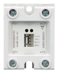
The Carlo Gavazzi RKD2A23D50C is a Double Pole Single Throw Solid State Relay (DPST SSR) designed for reliable and efficient switching of two independent circuits simultaneously. Unlike traditional mechanical relays, this SSR uses semiconductor components to provide fast, noise-free, and wear-resistant operation. It is ideal for applications requiring high-speed switching, electrical isolation, and long operational life.
Explore Projects Built with DPST SSR


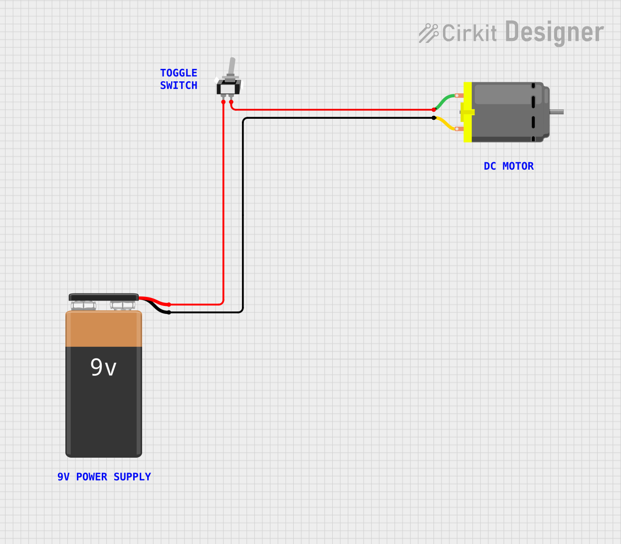
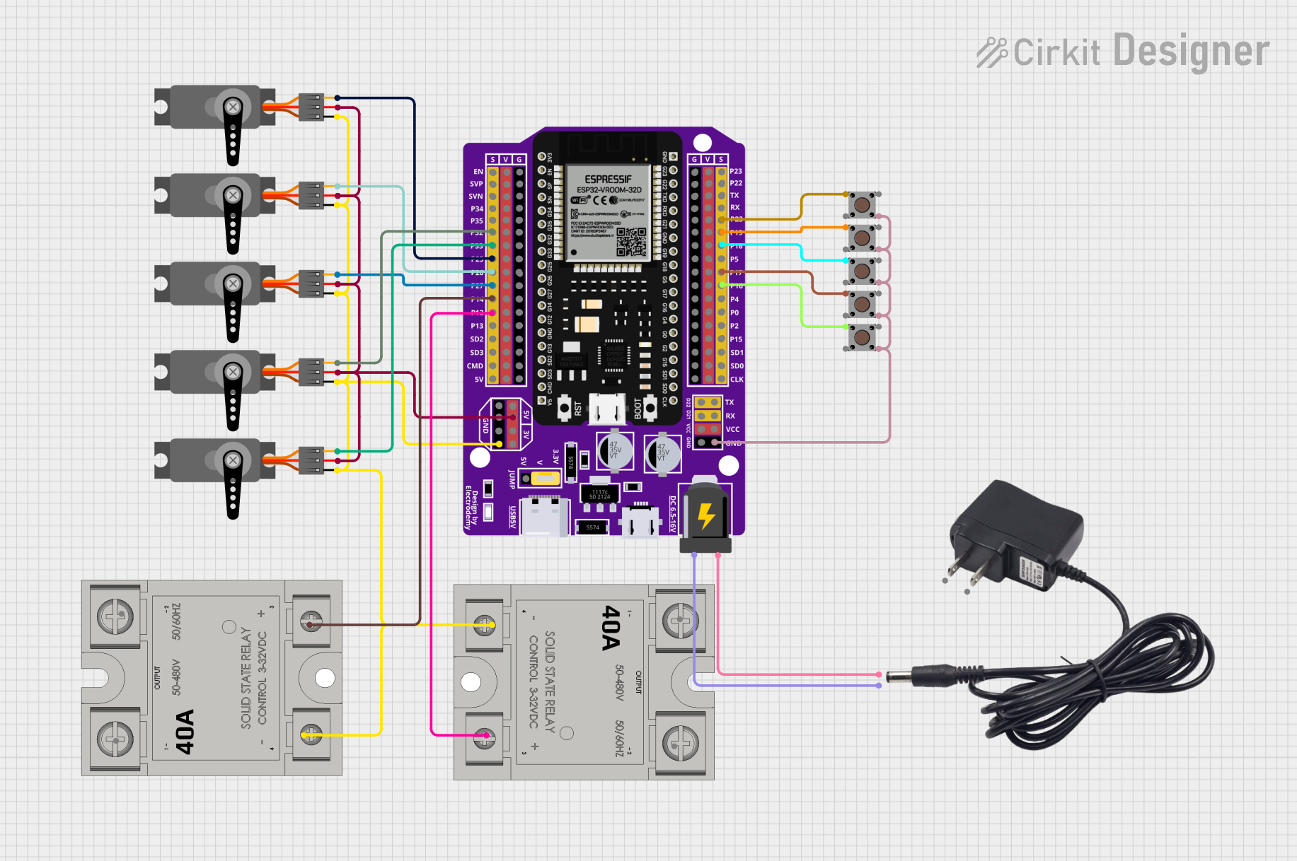
Explore Projects Built with DPST SSR
Common Applications and Use Cases
- Industrial automation and control systems
- Heating, ventilation, and air conditioning (HVAC) systems
- Motor control and protection
- Lighting control in commercial and industrial environments
- Power distribution and load management
Technical Specifications
The following table outlines the key technical specifications of the Carlo Gavazzi RKD2A23D50C DPST SSR:
| Parameter | Value |
|---|---|
| Manufacturer | Carlo Gavazzi |
| Part Number | RKD2A23D50C |
| Relay Type | Solid State Relay (SSR) |
| Configuration | Double Pole Single Throw (DPST) |
| Load Voltage Range | 24-230 VAC |
| Maximum Load Current | 50 A per pole |
| Control Voltage Range | 4-32 VDC |
| Isolation Voltage | 4000 VAC |
| Switching Type | Zero-crossing |
| Operating Temperature | -30°C to +80°C |
| Mounting Type | Panel Mount |
| Dimensions (L x W x H) | 45 mm x 58 mm x 30 mm |
Pin Configuration and Descriptions
The RKD2A23D50C features a straightforward pin layout for easy integration into circuits. The table below describes the pin configuration:
| Pin Number | Label | Description |
|---|---|---|
| 1 | Input+ | Positive terminal for the control signal (4-32 VDC). |
| 2 | Input- | Negative terminal for the control signal (ground). |
| 3 | Load 1 (L1) | First load terminal for the AC circuit (connected to the first pole). |
| 4 | Load 1 (T1) | Second load terminal for the AC circuit (connected to the first pole). |
| 5 | Load 2 (L2) | First load terminal for the second AC circuit (connected to the second pole). |
| 6 | Load 2 (T2) | Second load terminal for the second AC circuit (connected to the second pole). |
Usage Instructions
How to Use the Component in a Circuit
Control Signal Connection:
- Connect the control signal (4-32 VDC) to the
Input+andInput-terminals. Ensure the polarity is correct. - Use a current-limiting resistor if required to protect the control circuit.
- Connect the control signal (4-32 VDC) to the
Load Connection:
- Connect the first AC load to the
Load 1 (L1)andLoad 1 (T1)terminals. - Connect the second AC load to the
Load 2 (L2)andLoad 2 (T2)terminals. - Ensure the load voltage and current do not exceed the relay's rated specifications.
- Connect the first AC load to the
Mounting:
- Secure the relay to a panel or heatsink using the mounting holes provided.
- Use thermal paste or a thermal pad to improve heat dissipation if operating at high loads.
Power Up:
- Apply the control voltage to activate the relay. The relay will switch both poles simultaneously, allowing current to flow through the connected loads.
Important Considerations and Best Practices
- Ensure proper heat dissipation by mounting the relay on a heatsink if operating near the maximum load current.
- Use appropriate fuses or circuit breakers to protect the relay and connected loads.
- Verify that the control voltage is within the specified range (4-32 VDC) to avoid damage to the relay.
- Avoid exceeding the maximum load current (50 A per pole) to prevent overheating or failure.
- Use zero-crossing switching to minimize electrical noise and extend the life of connected devices.
Example: Connecting to an Arduino UNO
The RKD2A23D50C can be controlled using an Arduino UNO. Below is an example circuit and code to toggle the relay using a digital output pin:
Circuit Diagram
- Connect the
Input+terminal of the relay to Arduino pin 9. - Connect the
Input-terminal of the relay to the Arduino GND. - Connect the AC loads to the relay's load terminals as described above.
Arduino Code
// Define the relay control pin
const int relayPin = 9;

void setup() {
  // Set the relay pin as an output
  pinMode(relayPin, OUTPUT);

  // Initialize the relay in the OFF state
  digitalWrite(relayPin, LOW);
}

void loop() {
  // Turn the relay ON
  digitalWrite(relayPin, HIGH);
  delay(5000); // Keep the relay ON for 5 seconds

  // Turn the relay OFF
  digitalWrite(relayPin, LOW);
  delay(5000); // Keep the relay OFF for 5 seconds
}
Troubleshooting and FAQs
Common Issues and Solutions
Relay Not Switching:
- Verify that the control voltage is within the specified range (4-32 VDC).
- Check the polarity of the control signal connections.
- Ensure the Arduino or control circuit is functioning correctly.
Overheating:
- Ensure the relay is mounted on a heatsink or panel with adequate ventilation.
- Verify that the load current does not exceed 50 A per pole.
Load Not Powering On:
- Check the load connections to ensure they are secure and correctly wired.
- Confirm that the load voltage is within the relay's specified range (24-230 VAC).
Electrical Noise or Interference:
- Use zero-crossing switching to minimize noise.
- Add snubber circuits or filters if necessary to suppress transients.
FAQs
Q: Can this relay switch DC loads?
A: No, the RKD2A23D50C is designed for AC loads only. Switching DC loads may damage the relay.
Q: Is the relay suitable for inductive loads?
A: Yes, but ensure proper snubber circuits are used to suppress voltage spikes caused by inductive loads.
Q: Can I use this relay without a heatsink?
A: For low-current applications, a heatsink may not be necessary. However, for high-current loads, a heatsink is recommended to prevent overheating.
Q: What is zero-crossing switching?
A: Zero-crossing switching ensures the relay switches on or off when the AC voltage crosses zero, reducing electrical noise and wear on connected devices.