How to Use 2Pin Push Switch: Examples, Pinouts, and Specs
Introduction
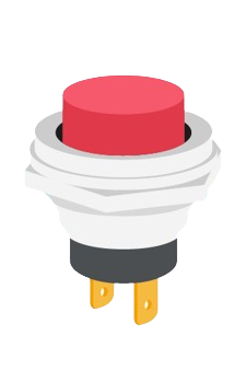
A 2-pin push switch, also known as a momentary switch, is a basic electronic component that creates a temporary electrical connection when pressed and breaks the connection when released. This type of switch is widely used in various applications such as consumer electronics, industrial controls, and hobbyist projects, including interfacing with microcontroller platforms like the Arduino UNO.
Explore Projects Built with 2Pin Push Switch
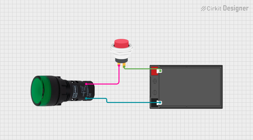
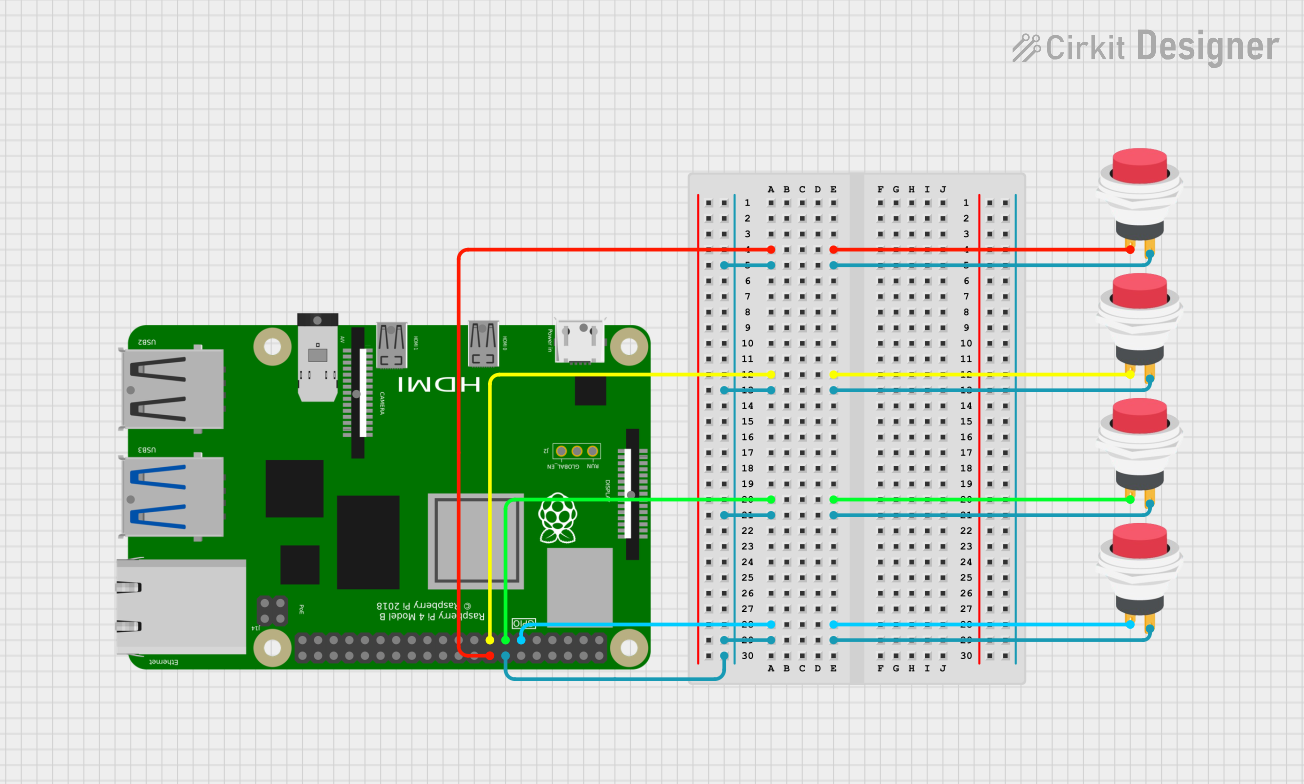
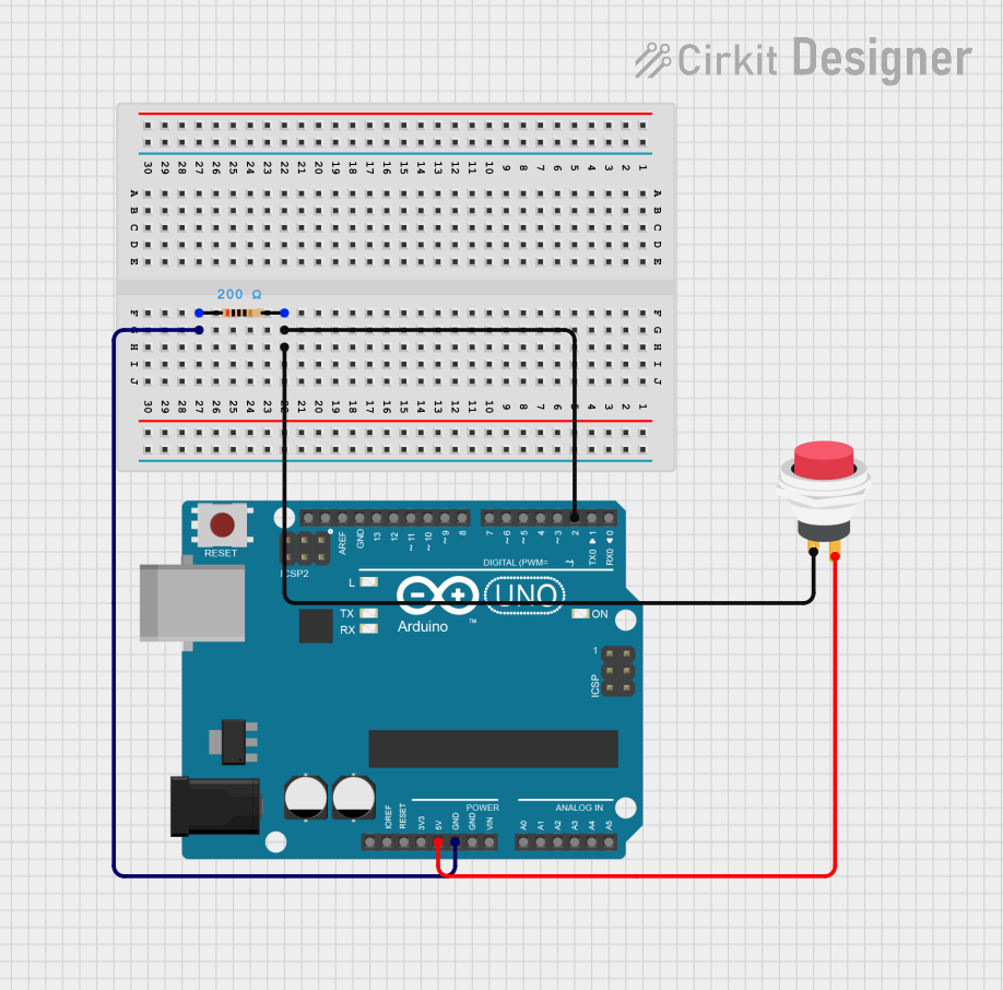

Explore Projects Built with 2Pin Push Switch
Common Applications and Use Cases
- User input for electronic devices
- Initiating a process or action in a circuit
- Reset or interrupt functions
- Prototyping and educational projects
Technical Specifications
Key Technical Details
- Contact Type: Momentary
- Contact Rating: Typically ranges from 50 mA to 1 A at 12-24 VDC
- Operating Force: Varies, commonly around 100-300 gf (grams force)
- Mechanical Life: Often rated for 100,000 to 1,000,000 cycles
- Operating Temperature: Usually -20°C to +70°C
Pin Configuration and Descriptions
| Pin Number | Description |
|---|---|
| 1 | Common terminal (C) |
| 2 | Normally open (NO) |
When the button is pressed, an electrical connection is made between pins 1 and 2.
Usage Instructions
How to Use the Component in a Circuit
- Identify the Pins: Determine which pin is the common terminal and which is the normally open terminal.
- Circuit Integration: Connect the common terminal to one side of the power source or signal line. Connect the normally open terminal to the load or the next component in the circuit.
- Debounce (Optional): Implement a debounce circuit or software debouncing to prevent multiple signals from being registered due to mechanical bounce.
Important Considerations and Best Practices
- Current Limiting: Ensure that the current through the switch does not exceed its rated value.
- Voltage Rating: Do not apply a voltage higher than the maximum rating of the switch.
- Mounting: Secure the switch firmly to prevent movement that could cause intermittent connections.
- Debouncing: To ensure a single clean signal, use hardware debouncing with a capacitor and resistor or software debouncing in the microcontroller code.
Example Code for Arduino UNO
// Define the pin connected to the push switch
const int pushSwitchPin = 2;

void setup() {
  // Set the push switch pin as an input
  pinMode(pushSwitchPin, INPUT_PULLUP);
  // Initialize serial communication at 9600 bits per second
  Serial.begin(9600);
}

void loop() {
  // Read the state of the push switch value
  int switchState = digitalRead(pushSwitchPin);

  // Check if the push switch is pressed (the pin will read low)
  if (switchState == LOW) {
    // If the switch is pressed, print a message
    Serial.println("Switch Pressed");
    // Delay a little to avoid bouncing issues
    delay(50);
  }
}
Note: The INPUT_PULLUP mode is used to enable the internal pull-up resistor, which ensures the pin is at a high state when the switch is not pressed.
Troubleshooting and FAQs
Common Issues Users Might Face
- Switch Bounce: Erratic behavior due to mechanical bouncing of the switch contacts.
- Intermittent Connections: Loose terminals or solder joints can cause unreliable operation.
- Exceeding Current Rating: Passing more current than the switch can handle may damage it.
Solutions and Tips for Troubleshooting
- Debouncing: Implement debouncing techniques to mitigate switch bounce.
- Secure Connections: Check and re-solder any loose connections.
- Current Limiting: Use a current limiting resistor or ensure the load does not draw more current than the switch's rating.
FAQs
Q: Can I use the switch with an AC voltage? A: This switch is typically rated for DC voltage. Using it with AC voltage may require a different type of switch.
Q: How do I know if my switch is damaged? A: A damaged switch may not make a connection when pressed or may have a charred or melted appearance.
Q: Is it necessary to debounce the switch in every application? A: Debouncing is recommended for digital circuits, especially when precise input is required. In some simple or slow applications, it may not be necessary.
Manufacturer: Electronics
Part ID: Electronics
Description: A 2-pin push switch is a simple momentary switch that is typically used to send a signal when pressed and released.