How to Use esp32 type c: Examples, Pinouts, and Specs
Introduction
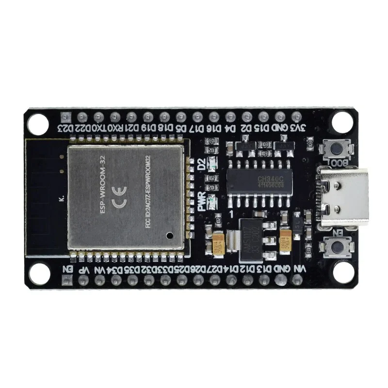
The ESP32 Type-C, manufactured by IRPANGTG, is a powerful and versatile microcontroller module designed for IoT (Internet of Things) applications. It features dual-core processing, integrated Wi-Fi and Bluetooth capabilities, and a USB Type-C interface for power and programming. This module is ideal for projects requiring wireless communication, low power consumption, and high processing power.
Common applications include:
- Smart home devices
- Wearable technology
- Industrial automation
- Wireless sensor networks
- Robotics and drones
Explore Projects Built with esp32 type c


Explore Projects Built with esp32 type c
Technical Specifications
The ESP32 Type-C offers the following key technical details:
| Specification | Details |
|---|---|
| Microcontroller | ESP32 dual-core Xtensa LX6 |
| Clock Speed | Up to 240 MHz |
| Flash Memory | 4 MB (expandable in some variants) |
| SRAM | 520 KB |
| Wireless Connectivity | Wi-Fi 802.11 b/g/n, Bluetooth 4.2 (Classic + BLE) |
| USB Interface | USB Type-C for power and programming |
| Operating Voltage | 3.3V |
| Input Voltage (via USB) | 5V |
| GPIO Pins | 30 (multipurpose, including ADC, DAC, PWM, etc.) |
| ADC Resolution | 12-bit |
| DAC Resolution | 8-bit |
| Power Consumption | Ultra-low power modes available |
| Dimensions | 25mm x 50mm |
Pin Configuration and Descriptions
The ESP32 Type-C module has a 30-pin layout. Below is the pin configuration:
| Pin Number | Pin Name | Description |
|---|---|---|
| 1 | GND | Ground |
| 2 | 3V3 | 3.3V power output |
| 3 | EN | Enable pin (active high) |
| 4 | IO0 | GPIO0, used for boot mode selection |
| 5 | IO1 | GPIO1, UART TXD |
| 6 | IO3 | GPIO3, UART RXD |
| 7 | IO4 | GPIO4, general-purpose I/O |
| 8 | IO5 | GPIO5, general-purpose I/O |
| 9 | IO12 | GPIO12, ADC2 channel 5 |
| 10 | IO13 | GPIO13, ADC2 channel 4 |
| 11 | IO14 | GPIO14, ADC2 channel 6 |
| 12 | IO15 | GPIO15, ADC2 channel 3 |
| 13 | IO16 | GPIO16, general-purpose I/O |
| 14 | IO17 | GPIO17, general-purpose I/O |
| 15 | IO18 | GPIO18, SPI CLK |
| 16 | IO19 | GPIO19, SPI MISO |
| 17 | IO21 | GPIO21, I2C SDA |
| 18 | IO22 | GPIO22, I2C SCL |
| 19 | IO23 | GPIO23, SPI MOSI |
| 20 | IO25 | GPIO25, DAC1 |
| 21 | IO26 | GPIO26, DAC2 |
| 22 | IO27 | GPIO27, ADC2 channel 7 |
| 23 | IO32 | GPIO32, ADC1 channel 4 |
| 24 | IO33 | GPIO33, ADC1 channel 5 |
| 25 | IO34 | GPIO34, ADC1 channel 6 (input only) |
| 26 | IO35 | GPIO35, ADC1 channel 7 (input only) |
| 27 | VIN | Input voltage (5V via USB Type-C) |
| 28 | TXD0 | UART0 TXD |
| 29 | RXD0 | UART0 RXD |
| 30 | RST | Reset pin |
Usage Instructions
How to Use the ESP32 Type-C in a Circuit
Powering the Module:
- Connect the ESP32 Type-C to a USB Type-C cable for power and programming.
- Alternatively, supply 3.3V to the
3V3pin or 5V to theVINpin.
Programming the Module:
- Use the Arduino IDE or ESP-IDF (Espressif IoT Development Framework) for programming.
- Install the necessary ESP32 board support package in the Arduino IDE.
- Connect the ESP32 Type-C to your computer via USB Type-C and select the appropriate COM port.
Connecting Peripherals:
- Use GPIO pins for interfacing with sensors, actuators, and other devices.
- Ensure that the voltage levels of connected peripherals are compatible with the 3.3V logic of the ESP32.
Flashing Code:
- Press and hold the
BOOTbutton (connected to GPIO0) while pressing theENbutton to enter bootloader mode. - Upload your code using the Arduino IDE or ESP-IDF.
- Press and hold the
Example Code for Arduino UNO Integration
Below is an example of using the ESP32 Type-C to read a temperature sensor and send data via Wi-Fi:
#include <WiFi.h> // Include the Wi-Fi library

// Replace with your network credentials
const char* ssid = "Your_SSID";
const char* password = "Your_PASSWORD";

void setup() {
  Serial.begin(115200); // Initialize serial communication at 115200 baud
  WiFi.begin(ssid, password); // Connect to Wi-Fi network

  // Wait for connection
  while (WiFi.status() != WL_CONNECTED) {
    delay(1000);
    Serial.println("Connecting to Wi-Fi...");
  }
  Serial.println("Connected to Wi-Fi!");
}

void loop() {
  // Example: Print the IP address of the ESP32
  Serial.println(WiFi.localIP());
  delay(5000); // Wait for 5 seconds before printing again
}
Important Considerations and Best Practices
- Always use a level shifter when interfacing 5V devices with the ESP32's 3.3V GPIO pins.
- Avoid drawing excessive current from the
3V3pin to prevent instability. - Use proper decoupling capacitors near the power pins to reduce noise.
- Ensure the antenna area is free from obstructions for optimal Wi-Fi and Bluetooth performance.
Troubleshooting and FAQs
Common Issues and Solutions
ESP32 Not Detected by Computer:
- Ensure the USB Type-C cable supports data transfer (not just charging).
- Check if the correct drivers for the ESP32 are installed on your computer.
Code Upload Fails:
- Verify that the correct COM port is selected in the Arduino IDE.
- Hold the
BOOTbutton while pressing theENbutton to enter bootloader mode.
Wi-Fi Connection Issues:
- Double-check the SSID and password in your code.
- Ensure the Wi-Fi network is within range and not overloaded.
Overheating:
- Avoid overloading the GPIO pins or drawing excessive current.
- Use proper heat dissipation techniques if the module operates in high-temperature environments.
FAQs
Q: Can the ESP32 Type-C be powered directly from a battery?
A: Yes, you can power the module using a 3.7V LiPo battery connected to the VIN pin, but ensure proper voltage regulation.
Q: Does the ESP32 Type-C support OTA (Over-the-Air) updates?
A: Yes, the ESP32 supports OTA updates, which can be implemented using the Arduino IDE or ESP-IDF.
Q: Can I use the ESP32 Type-C for Bluetooth audio applications?
A: Yes, the ESP32 supports Bluetooth audio streaming, but additional libraries and configurations may be required.
Q: What is the maximum range of the Wi-Fi module?
A: The Wi-Fi range is approximately 50 meters indoors and up to 200 meters outdoors, depending on environmental factors.