Cirkit Designer Logo
Cirkit Designer
Your all-in-one circuit design IDE
Home / 
Component Documentation

How to Use Wheatstone Bridge Phidget: Examples, Pinouts, and Specs

Image of Wheatstone Bridge Phidget
Cirkit Designer LogoDesign with Wheatstone Bridge Phidget in Cirkit Designer

Introduction

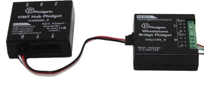
The Wheatstone Bridge Phidget (Manufacturer Part ID: Load Cell Amplifier) is a precision device designed to measure resistance by balancing two legs of a bridge circuit. It is widely used in applications requiring accurate detection of small resistance changes, such as strain gauges, load cells, and temperature sensors. This component is ideal for scenarios where precise measurements of physical parameters like force, pressure, or temperature are required.

Explore Projects Built with Wheatstone Bridge Phidget

Use Cirkit Designer to design, explore, and prototype these projects online. Some projects support real-time simulation. Click "Open Project" to start designing instantly!
VINT Hub-Controlled Multi-Stepper Motor System
Image of ENPH454: A project utilizing Wheatstone Bridge Phidget in a practical application
This circuit consists of a VINT Hub Phidget connected to four 4A Stepper Phidgets, which in turn are connected to four NEMA23 stepper motors. The VINT Hub Phidget interfaces with the stepper controllers, likely for the purpose of controlling the stepper motors. A power supply is connected to all the stepper controllers to provide the necessary voltage, and a Square FSR (Force Sensitive Resistor) with a resistor is connected to the VINT Hub, possibly for sensing force or pressure.
Cirkit Designer LogoOpen Project in Cirkit Designer
Raspberry Pi 4B-Based Multi-Sensor Data Acquisition and Display System
Image of test: A project utilizing Wheatstone Bridge Phidget in a practical application
This circuit features a Raspberry Pi 4B as the central controller, interfaced with various sensors including a DS18B20 temperature sensor, AHT10 humidity sensor, Adafruit ADXL345 accelerometer, and SW-420 vibration sensor. It also includes multiple HX711 bridge sensor interfaces connected to load cells for weight measurement, a TFT LCD display for output, and a ULN2003A breakout board likely for driving a stepper motor or similar inductive load. Power management is handled by a 12V 5A power supply with PTCs for protection, and a MB102 breadboard power supply module providing 3.3V/5V levels. The circuit is designed for monitoring environmental conditions, weight, and vibrations, with visual feedback and potential for motion control applications.
Cirkit Designer LogoOpen Project in Cirkit Designer
Arduino-Controlled Load Cell Measurement System with Relay-Activated Indicator Lamps
Image of ww: A project utilizing Wheatstone Bridge Phidget in a practical application
This circuit is designed to measure weight using a load cell interfaced with an HX711 bridge sensor interface, which is connected to an Arduino UNO microcontroller for data processing. The Arduino controls a 2-channel relay module that can switch pilot lamps (one green, one red) based on the weight measurements or other programmed conditions. The relay module is powered by the Arduino's 5V supply, and the HX711 is powered by the same line, indicating it operates at 3.3V or 5V as needed.
Cirkit Designer LogoOpen Project in Cirkit Designer
Arduino Nano Based Weight Scale with HX711 and I2C LCD Display
Image of ds: A project utilizing Wheatstone Bridge Phidget in a practical application
This circuit is designed to measure weight using a load cell interfaced with an HX711 bridge sensor interface, which is connected to an Arduino Nano microcontroller. The Arduino processes the signal from the HX711 and displays the measured weight on a 16x2 I2C LCD. The system is powered by a 9V battery, and the Arduino communicates with the LCD via I2C protocol and with the HX711 using digital input/output pins.
Cirkit Designer LogoOpen Project in Cirkit Designer

Explore Projects Built with Wheatstone Bridge Phidget

Use Cirkit Designer to design, explore, and prototype these projects online. Some projects support real-time simulation. Click "Open Project" to start designing instantly!
Image of ENPH454: A project utilizing Wheatstone Bridge Phidget in a practical application
VINT Hub-Controlled Multi-Stepper Motor System
This circuit consists of a VINT Hub Phidget connected to four 4A Stepper Phidgets, which in turn are connected to four NEMA23 stepper motors. The VINT Hub Phidget interfaces with the stepper controllers, likely for the purpose of controlling the stepper motors. A power supply is connected to all the stepper controllers to provide the necessary voltage, and a Square FSR (Force Sensitive Resistor) with a resistor is connected to the VINT Hub, possibly for sensing force or pressure.
Cirkit Designer LogoOpen Project in Cirkit Designer
Image of test: A project utilizing Wheatstone Bridge Phidget in a practical application
Raspberry Pi 4B-Based Multi-Sensor Data Acquisition and Display System
This circuit features a Raspberry Pi 4B as the central controller, interfaced with various sensors including a DS18B20 temperature sensor, AHT10 humidity sensor, Adafruit ADXL345 accelerometer, and SW-420 vibration sensor. It also includes multiple HX711 bridge sensor interfaces connected to load cells for weight measurement, a TFT LCD display for output, and a ULN2003A breakout board likely for driving a stepper motor or similar inductive load. Power management is handled by a 12V 5A power supply with PTCs for protection, and a MB102 breadboard power supply module providing 3.3V/5V levels. The circuit is designed for monitoring environmental conditions, weight, and vibrations, with visual feedback and potential for motion control applications.
Cirkit Designer LogoOpen Project in Cirkit Designer
Image of ww: A project utilizing Wheatstone Bridge Phidget in a practical application
Arduino-Controlled Load Cell Measurement System with Relay-Activated Indicator Lamps
This circuit is designed to measure weight using a load cell interfaced with an HX711 bridge sensor interface, which is connected to an Arduino UNO microcontroller for data processing. The Arduino controls a 2-channel relay module that can switch pilot lamps (one green, one red) based on the weight measurements or other programmed conditions. The relay module is powered by the Arduino's 5V supply, and the HX711 is powered by the same line, indicating it operates at 3.3V or 5V as needed.
Cirkit Designer LogoOpen Project in Cirkit Designer
Image of ds: A project utilizing Wheatstone Bridge Phidget in a practical application
Arduino Nano Based Weight Scale with HX711 and I2C LCD Display
This circuit is designed to measure weight using a load cell interfaced with an HX711 bridge sensor interface, which is connected to an Arduino Nano microcontroller. The Arduino processes the signal from the HX711 and displays the measured weight on a 16x2 I2C LCD. The system is powered by a 9V battery, and the Arduino communicates with the LCD via I2C protocol and with the HX711 using digital input/output pins.
Cirkit Designer LogoOpen Project in Cirkit Designer

Common Applications and Use Cases

  • Strain Gauges: Measuring deformation or strain in materials.
  • Load Cells: Detecting weight or force in industrial and laboratory settings.
  • Temperature Sensors: Monitoring temperature changes using resistive temperature devices (RTDs).
  • Pressure Sensors: Measuring pressure variations in fluid systems.
  • Scientific Research: High-precision resistance measurements in experimental setups.

Technical Specifications

The following table outlines the key technical details of the Wheatstone Bridge Phidget:

Parameter Value
Supply Voltage 5V DC
Operating Current 20 mA (typical)
Input Resistance Range 350 Ω to 10 kΩ
Output Signal Range 0 to 5V
Amplification Factor Configurable (default: 128x)
Operating Temperature -40°C to 85°C
Interface Analog Output

Pin Configuration and Descriptions

The Wheatstone Bridge Phidget has a simple pinout for easy integration into circuits. The table below describes each pin:

Pin Name Description
VCC Power supply input (5V DC).
GND Ground connection.
SIG+ Positive signal input from the sensor (e.g., strain gauge).
SIG- Negative signal input from the sensor.
OUT Analog output signal proportional to the resistance imbalance in the bridge.

Usage Instructions

How to Use the Component in a Circuit

  1. Power the Device: Connect the VCC pin to a 5V DC power source and the GND pin to ground.
  2. Connect the Sensor: Attach the resistive sensor (e.g., strain gauge or load cell) to the SIG+ and SIG- pins. Ensure proper polarity and secure connections.
  3. Read the Output: The OUT pin provides an analog voltage signal proportional to the resistance imbalance in the Wheatstone bridge. This signal can be read using an analog-to-digital converter (ADC) or a microcontroller like an Arduino.

Important Considerations and Best Practices

  • Calibration: Always calibrate the system with known reference values to ensure accurate measurements.
  • Shielding: Use shielded cables for the sensor connections to minimize noise and interference.
  • Amplification: Adjust the amplification factor if your application requires a higher or lower sensitivity.
  • Temperature Compensation: If using in environments with varying temperatures, consider implementing temperature compensation to maintain accuracy.
  • Load Cell Wiring: For load cells, ensure the wiring matches the manufacturer's specifications (e.g., excitation and signal wires).

Example: Connecting to an Arduino UNO

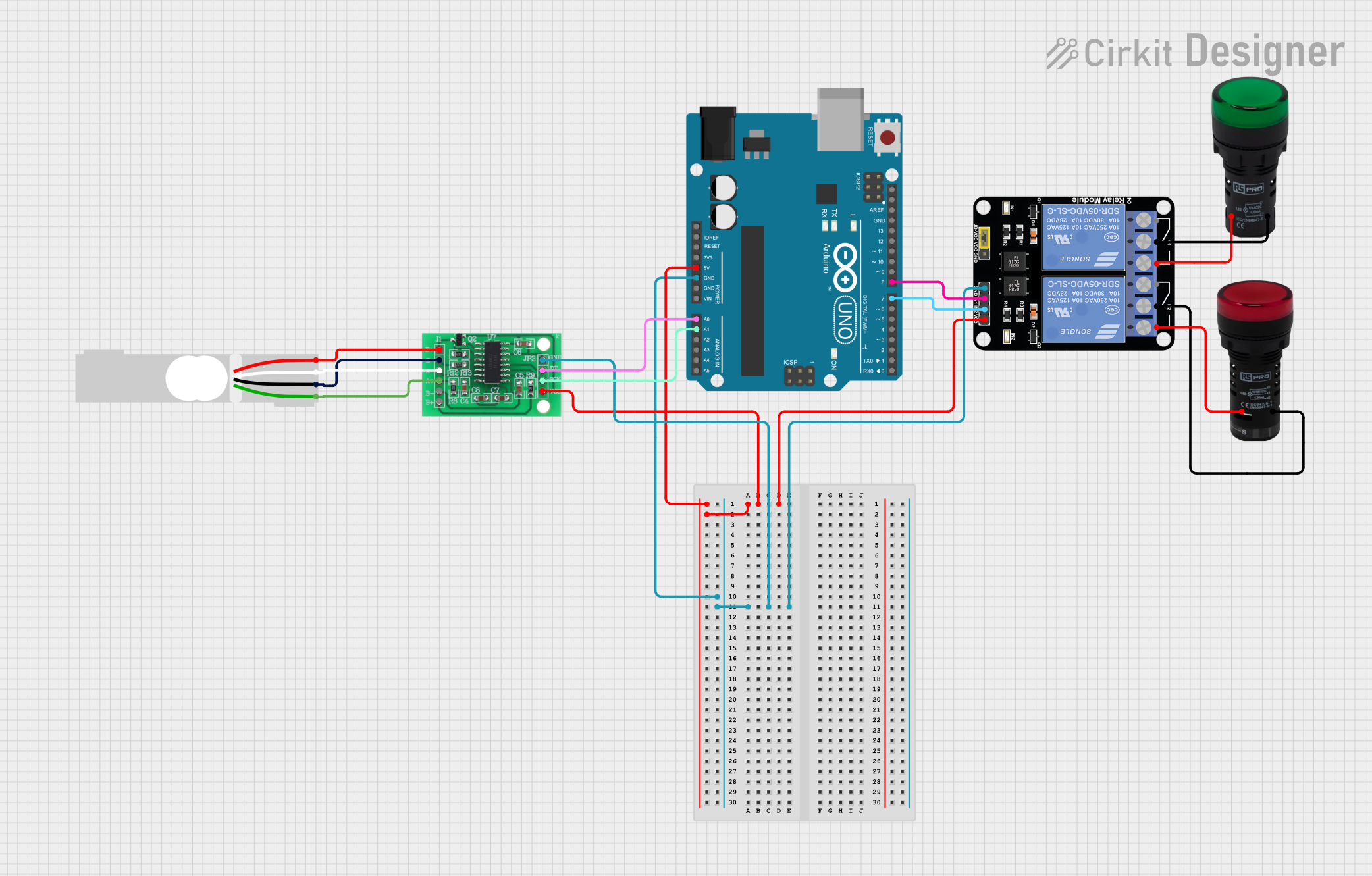
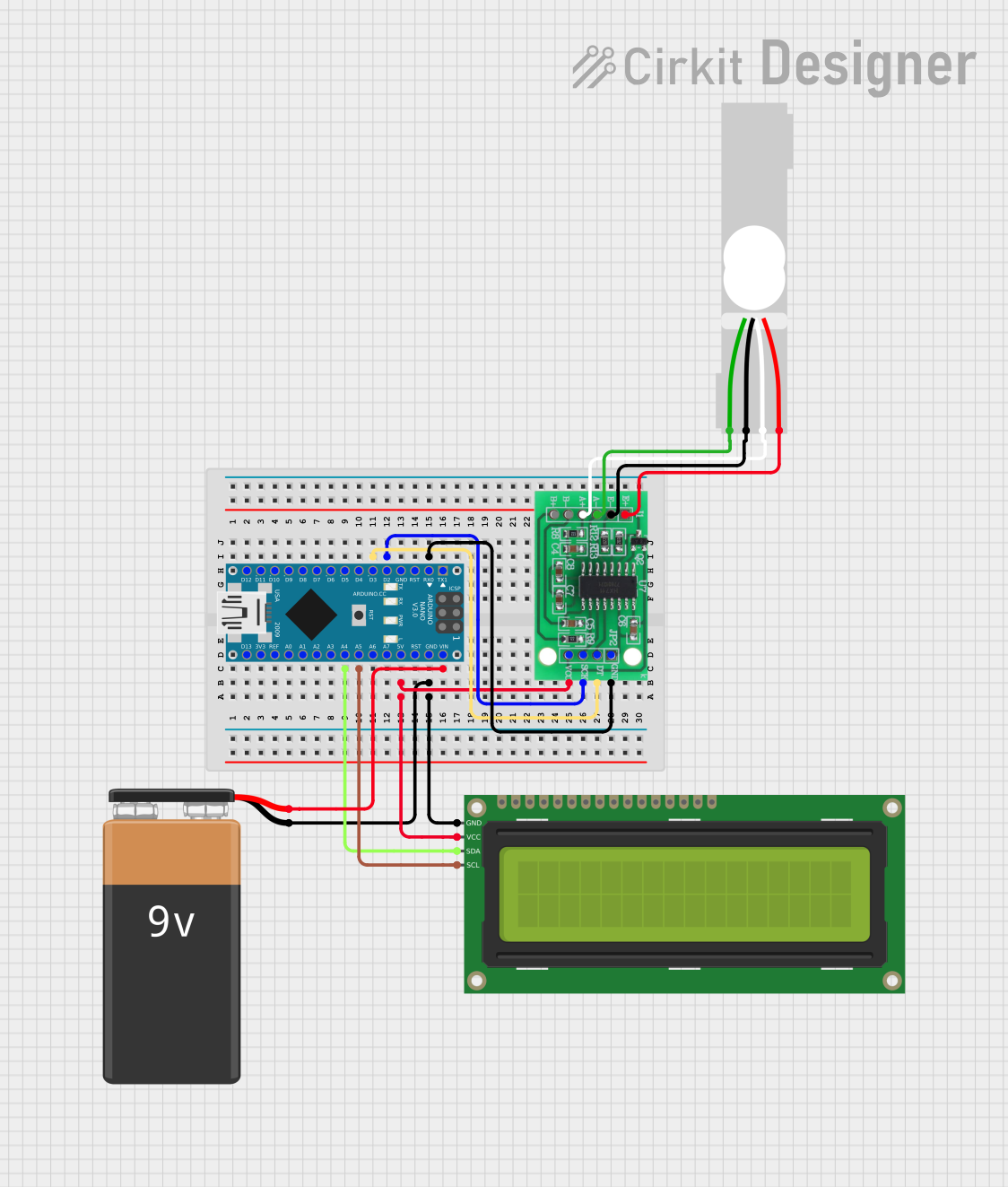
Below is an example of how to connect the Wheatstone Bridge Phidget to an Arduino UNO and read the output signal:

Circuit Diagram

  • VCC → Arduino 5V
  • GND → Arduino GND
  • OUT → Arduino A0 (Analog Pin)
  • SIG+ and SIG- → Connected to the resistive sensor (e.g., strain gauge).

Arduino Code

// Define the analog pin connected to the OUT pin of the Wheatstone Bridge Phidget
const int analogPin = A0;

void setup() {
  Serial.begin(9600); // Initialize serial communication at 9600 baud
}

void loop() {
  // Read the analog value from the Wheatstone Bridge Phidget
  int sensorValue = analogRead(analogPin);

  // Convert the analog value to a voltage (assuming 5V reference)
  float voltage = sensorValue * (5.0 / 1023.0);

  // Print the voltage to the Serial Monitor
  Serial.print("Voltage: ");
  Serial.print(voltage);
  Serial.println(" V");

  delay(500); // Wait for 500ms before the next reading
}

Troubleshooting and FAQs

Common Issues and Solutions

  1. No Output Signal:

    • Cause: Incorrect wiring or loose connections.
    • Solution: Double-check all connections, especially the sensor wiring to SIG+ and SIG-.
  2. Fluctuating Readings:

    • Cause: Electrical noise or interference.
    • Solution: Use shielded cables and ensure proper grounding.
  3. Inaccurate Measurements:

    • Cause: Lack of calibration or temperature effects.
    • Solution: Calibrate the system with known reference values and implement temperature compensation if necessary.
  4. Output Signal Saturation:

    • Cause: Amplification factor too high.
    • Solution: Reduce the amplification factor or use a sensor with a higher resistance range.

FAQs

Q: Can I use this component with a 3.3V microcontroller?
A: Yes, but ensure the output signal range (0-5V) is compatible with the ADC input range of your microcontroller. You may need a voltage divider or level shifter.

Q: How do I adjust the amplification factor?
A: The amplification factor can typically be adjusted via onboard jumpers or potentiometers. Refer to the manufacturer's datasheet for specific instructions.

Q: Is this component suitable for dynamic measurements?
A: Yes, but ensure the sampling rate of your ADC is sufficient to capture the changes in the output signal.

Q: Can I use multiple Wheatstone Bridge Phidgets in the same system?
A: Yes, but ensure each device has a dedicated ADC input and proper isolation to avoid interference.

This concludes the documentation for the Wheatstone Bridge Phidget. For further assistance, refer to the manufacturer's datasheet or support resources.