How to Use FDC2214: Examples, Pinouts, and Specs
Introduction
The FDC2214 is a high-precision capacitance-to-digital converter (CDC) designed to measure capacitance with exceptional resolution and speed. It operates by converting small changes in capacitance into a digital output, making it ideal for applications requiring high sensitivity and accuracy. The FDC2214 is commonly used in proximity sensing, liquid level sensing, and touch sensing applications. Its digital output simplifies integration into microcontroller-based systems, enabling efficient and reliable designs.
Explore Projects Built with FDC2214


Explore Projects Built with FDC2214
Technical Specifications
The FDC2214 offers robust performance and flexibility for a wide range of sensing applications. Below are its key technical specifications:
Key Features
- Supply Voltage: 2.7 V to 3.6 V
- Operating Temperature: -40°C to +125°C
- Capacitance Measurement Range: Up to 250 nF
- Resolution: 28 bits
- Interface: I²C
- Channels: 4 independent input channels
- Conversion Rate: Up to 4.08 kSPS (kilo-samples per second)
- Output Format: Digital (I²C-compatible)
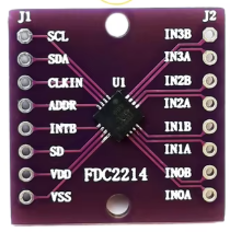
Pin Configuration and Descriptions
The FDC2214 is available in a 16-pin WQFN package. Below is the pinout and description:
| Pin | Name | Type | Description |
|---|---|---|---|
| 1 | IN0A | Input | Positive input for channel 0. Connect to the sensing electrode. |
| 2 | IN0B | Input | Negative input for channel 0. Connect to ground or a reference electrode. |
| 3 | IN1A | Input | Positive input for channel 1. Connect to the sensing electrode. |
| 4 | IN1B | Input | Negative input for channel 1. Connect to ground or a reference electrode. |
| 5 | IN2A | Input | Positive input for channel 2. Connect to the sensing electrode. |
| 6 | IN2B | Input | Negative input for channel 2. Connect to ground or a reference electrode. |
| 7 | IN3A | Input | Positive input for channel 3. Connect to the sensing electrode. |
| 8 | IN3B | Input | Negative input for channel 3. Connect to ground or a reference electrode. |
| 9 | GND | Ground | Ground connection. |
| 10 | VDD | Power | Power supply input (2.7 V to 3.6 V). |
| 11 | SDA | I²C Data Line | Serial data line for I²C communication. |
| 12 | SCL | I²C Clock Line | Serial clock line for I²C communication. |
| 13 | ADDR | Input | I²C address selection pin. |
| 14 | INTB | Output | Interrupt output (active low). |
| 15 | CLKIN | Input | External clock input (optional). |
| 16 | NC | No Connection | Not connected internally. Leave floating. |
Usage Instructions
The FDC2214 is straightforward to use in a circuit, but proper configuration and design considerations are essential for optimal performance.
How to Use the FDC2214 in a Circuit
- Power Supply: Connect the VDD pin to a 3.3 V power supply and the GND pin to ground.
- Capacitive Sensors: Connect the sensing electrodes to the INxA pins and reference electrodes (or ground) to the corresponding INxB pins.
- I²C Communication: Connect the SDA and SCL pins to the I²C bus of your microcontroller. Use pull-up resistors (typically 4.7 kΩ) on both lines.
- Address Selection: Set the ADDR pin to configure the I²C address. This allows multiple FDC2214 devices on the same I²C bus.
- Interrupts: If needed, connect the INTB pin to a GPIO pin on your microcontroller to handle interrupts.
- External Clock (Optional): If an external clock is required, connect it to the CLKIN pin.
Best Practices
- Use proper shielding and grounding to minimize noise and interference in capacitive measurements.
- Ensure the sensing electrodes are designed to match the application's requirements (e.g., size, shape, and material).
- Place decoupling capacitors (e.g., 0.1 µF) close to the VDD pin to stabilize the power supply.
- Avoid long traces for the sensing electrodes to reduce parasitic capacitance and signal loss.
Example: Connecting the FDC2214 to an Arduino UNO
Below is an example of how to interface the FDC2214 with an Arduino UNO using the I²C protocol:
Circuit Connections
- Connect the FDC2214's SDA pin to Arduino's A4 (SDA).
- Connect the FDC2214's SCL pin to Arduino's A5 (SCL).
- Connect the VDD pin to the Arduino's 3.3 V pin.
- Connect the GND pin to the Arduino's GND.
Arduino Code Example
#include <Wire.h>

// FDC2214 I2C address (default is 0x2A, depending on ADDR pin configuration)
#define FDC2214_I2C_ADDR 0x2A

void setup() {
  Wire.begin(); // Initialize I2C communication
  Serial.begin(9600); // Initialize serial communication for debugging

  // Configure the FDC2214 (example: setting up channel 0)
  Wire.beginTransmission(FDC2214_I2C_ADDR);
  Wire.write(0x08); // Address of the configuration register for channel 0
  Wire.write(0x1E); // Example configuration value (high byte)
  Wire.write(0x00); // Example configuration value (low byte)
  Wire.endTransmission();

  Serial.println("FDC2214 initialized.");
}

void loop() {
  // Read data from the FDC2214
  Wire.beginTransmission(FDC2214_I2C_ADDR);
  Wire.write(0x00); // Address of the data register for channel 0
  Wire.endTransmission();

  Wire.requestFrom(FDC2214_I2C_ADDR, 2); // Request 2 bytes of data
  if (Wire.available() == 2) {
    uint16_t data = (Wire.read() << 8) | Wire.read(); // Combine high and low bytes
    Serial.print("Capacitance Data: ");
    Serial.println(data);
  }

  delay(500); // Wait before the next reading
}
Notes
- Modify the configuration register values in the code to suit your specific application.
- Ensure the I²C address matches the configuration of the ADDR pin.
Troubleshooting and FAQs
Common Issues
No Response from the FDC2214
- Solution: Verify the I²C connections (SDA, SCL) and ensure pull-up resistors are present.
- Solution: Check the power supply voltage (2.7 V to 3.6 V) and ensure proper grounding.
Inaccurate Capacitance Measurements
- Solution: Ensure the sensing electrodes are properly designed and free from external interference.
- Solution: Verify that the input channels are correctly configured in the software.
I²C Communication Errors
- Solution: Check the I²C address configuration (ADDR pin) and ensure it matches the software settings.
- Solution: Use an oscilloscope to verify the integrity of the I²C signals.
FAQs
Can the FDC2214 measure multiple channels simultaneously?
- Yes, the FDC2214 supports up to 4 independent input channels, which can be configured and read sequentially.
What is the maximum capacitance the FDC2214 can measure?
- The FDC2214 can measure capacitance up to 250 nF, depending on the configuration.
Is an external clock required for the FDC2214?
- No, the FDC2214 has an internal oscillator. However, an external clock can be used for specific applications requiring precise timing.
By following this documentation, users can effectively integrate the FDC2214 into their designs and troubleshoot common issues.