Cirkit Designer Logo
Cirkit Designer
Your all-in-one circuit design IDE
Home / 
Component Documentation

How to Use JMOD-128_N: Examples, Pinouts, and Specs

Image of JMOD-128_N
Cirkit Designer LogoDesign with JMOD-128_N in Cirkit Designer

Introduction

The JMOD-128_N is a high-performance, low-noise operational amplifier designed by JCNET. This component is ideal for precision applications, featuring a wide bandwidth and low offset voltage. It is particularly suitable for use in signal conditioning and data acquisition systems, where accuracy and stability are paramount.

Explore Projects Built with JMOD-128_N

Use Cirkit Designer to design, explore, and prototype these projects online. Some projects support real-time simulation. Click "Open Project" to start designing instantly!
Battery-Powered Emergency Alert System with NUCLEO-F072RB, SIM800L, and GPS NEO 6M
Image of women safety: A project utilizing JMOD-128_N in a practical application
This circuit is an emergency alert system that uses a NUCLEO-F072RB microcontroller to send SMS alerts and make calls via a SIM800L GSM module, while obtaining location data from a GPS NEO 6M module. The system is powered by a Li-ion battery and includes a TP4056 module for battery charging and protection, with a rocker switch to control power to the microcontroller.
Cirkit Designer LogoOpen Project in Cirkit Designer
DC-DC Converter and Relay Module Power Distribution System
Image of relay: A project utilizing JMOD-128_N in a practical application
This circuit consists of a DC-DC converter powering a 6-channel power module, which in turn supplies 5V to a 2-relay module. The power module distributes the converted voltage to the relay module, enabling it to control external devices.
Cirkit Designer LogoOpen Project in Cirkit Designer
NFC-Enabled Access Control System with Time Logging
Image of doorlock: A project utilizing JMOD-128_N in a practical application
This circuit is designed for access control with time tracking capabilities. It features an NFC/RFID reader for authentication, an RTC module (DS3231) for real-time clock functionality, and an OLED display for user interaction. A 12V relay controls a magnetic lock, which is activated upon successful NFC/RFID authentication, and a button switch is likely used for manual operation or input. The T8_S3 microcontroller serves as the central processing unit, interfacing with the NFC/RFID reader, RTC, OLED, and relay to manage the access control logic.
Cirkit Designer LogoOpen Project in Cirkit Designer
NFC-Enabled Access Control System with Real-Time Clock and OLED Display
Image of doorlock: A project utilizing JMOD-128_N in a practical application
This circuit is designed as an access control system with time-tracking capabilities. It uses an NFC/RFID reader for authentication, a real-time clock for time-stamping events, and an OLED display for user interface, all controlled by a T8_S3 microcontroller. A relay module actuates a magnetic lock, and a button switch provides additional user input, with a switching power supply delivering the necessary voltages.
Cirkit Designer LogoOpen Project in Cirkit Designer

Explore Projects Built with JMOD-128_N

Use Cirkit Designer to design, explore, and prototype these projects online. Some projects support real-time simulation. Click "Open Project" to start designing instantly!
Image of women safety: A project utilizing JMOD-128_N in a practical application
Battery-Powered Emergency Alert System with NUCLEO-F072RB, SIM800L, and GPS NEO 6M
This circuit is an emergency alert system that uses a NUCLEO-F072RB microcontroller to send SMS alerts and make calls via a SIM800L GSM module, while obtaining location data from a GPS NEO 6M module. The system is powered by a Li-ion battery and includes a TP4056 module for battery charging and protection, with a rocker switch to control power to the microcontroller.
Cirkit Designer LogoOpen Project in Cirkit Designer
Image of relay: A project utilizing JMOD-128_N in a practical application
DC-DC Converter and Relay Module Power Distribution System
This circuit consists of a DC-DC converter powering a 6-channel power module, which in turn supplies 5V to a 2-relay module. The power module distributes the converted voltage to the relay module, enabling it to control external devices.
Cirkit Designer LogoOpen Project in Cirkit Designer
Image of doorlock: A project utilizing JMOD-128_N in a practical application
NFC-Enabled Access Control System with Time Logging
This circuit is designed for access control with time tracking capabilities. It features an NFC/RFID reader for authentication, an RTC module (DS3231) for real-time clock functionality, and an OLED display for user interaction. A 12V relay controls a magnetic lock, which is activated upon successful NFC/RFID authentication, and a button switch is likely used for manual operation or input. The T8_S3 microcontroller serves as the central processing unit, interfacing with the NFC/RFID reader, RTC, OLED, and relay to manage the access control logic.
Cirkit Designer LogoOpen Project in Cirkit Designer
Image of doorlock: A project utilizing JMOD-128_N in a practical application
NFC-Enabled Access Control System with Real-Time Clock and OLED Display
This circuit is designed as an access control system with time-tracking capabilities. It uses an NFC/RFID reader for authentication, a real-time clock for time-stamping events, and an OLED display for user interface, all controlled by a T8_S3 microcontroller. A relay module actuates a magnetic lock, and a button switch provides additional user input, with a switching power supply delivering the necessary voltages.
Cirkit Designer LogoOpen Project in Cirkit Designer

Common Applications

  • Signal Conditioning
  • Data Acquisition Systems
  • Medical Instrumentation
  • Audio Equipment
  • Industrial Control Systems

Technical Specifications

Key Technical Details

Parameter Value
Supply Voltage ±5V to ±15V
Input Offset Voltage 0.5 mV (typical)
Input Bias Current 2 nA (typical)
Bandwidth 10 MHz
Slew Rate 20 V/µs
Noise Density 2.5 nV/√Hz
Output Current ±20 mA
Operating Temperature -40°C to +85°C

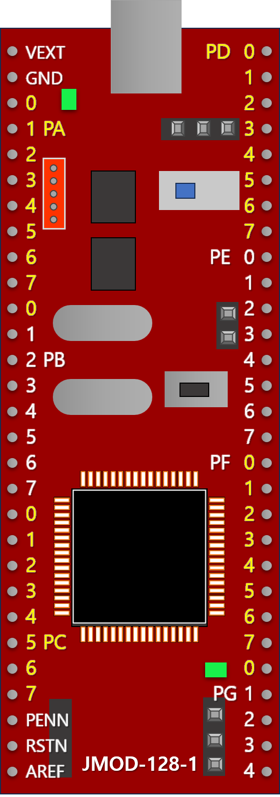
Pin Configuration and Descriptions

Pin Number Pin Name Description
1 Offset N Offset Null (Negative)
2 Inverting Input Inverting Input of the Op-Amp
3 Non-Inverting Input Non-Inverting Input of the Op-Amp
4 V- Negative Power Supply
5 Offset P Offset Null (Positive)
6 Output Output of the Op-Amp
7 V+ Positive Power Supply
8 NC No Connection

Usage Instructions

How to Use the Component in a Circuit

  1. Power Supply: Connect the V+ pin to the positive supply voltage (e.g., +15V) and the V- pin to the negative supply voltage (e.g., -15V).
  2. Input Connections: Connect your signal to the inverting (Pin 2) or non-inverting input (Pin 3) as required by your application.
  3. Output Connection: The output signal will be available at Pin 6.
  4. Offset Nulling: If precise offset voltage adjustment is needed, connect a potentiometer between Offset N (Pin 1) and Offset P (Pin 5), with the wiper connected to a stable reference voltage.

Important Considerations and Best Practices

  • Decoupling Capacitors: Place decoupling capacitors (e.g., 0.1 µF ceramic) close to the power supply pins to filter out noise.
  • PCB Layout: Ensure a clean and low-noise PCB layout by keeping signal paths short and using a ground plane.
  • Thermal Management: Ensure adequate cooling if the op-amp is used in high-power applications to prevent overheating.

Example Circuit with Arduino UNO

Below is an example of how to use the JMOD-128_N with an Arduino UNO to amplify a sensor signal.

// Example code to read an amplified sensor signal using Arduino UNO

const int sensorPin = A0; // Analog input pin for the sensor signal
int sensorValue = 0;      // Variable to store the sensor value

void setup() {
  Serial.begin(9600); // Initialize serial communication at 9600 baud
}

void loop() {
  sensorValue = analogRead(sensorPin); // Read the sensor value
  Serial.print("Sensor Value: ");
  Serial.println(sensorValue); // Print the sensor value to the serial monitor
  delay(1000); // Wait for 1 second before the next reading
}

Troubleshooting and FAQs

Common Issues and Solutions

  1. No Output Signal:

    • Check Power Supply: Ensure that the V+ and V- pins are connected to the correct supply voltages.
    • Verify Connections: Double-check all input and output connections.
  2. High Noise Levels:

    • Use Decoupling Capacitors: Place capacitors close to the power supply pins.
    • Improve PCB Layout: Minimize the length of signal paths and use a ground plane.
  3. Offset Voltage Too High:

    • Adjust Offset Null: Use a potentiometer between Offset N and Offset P pins to fine-tune the offset voltage.

FAQs

Q1: Can I use the JMOD-128_N with a single power supply?

  • A1: Yes, the JMOD-128_N can be used with a single power supply. Connect the V- pin to ground and the V+ pin to the positive supply voltage.

Q2: What is the maximum output current of the JMOD-128_N?

  • A2: The maximum output current is ±20 mA.

Q3: How do I minimize the noise in my circuit?

  • A3: Use decoupling capacitors close to the power supply pins, keep signal paths short, and use a ground plane in your PCB layout.

This documentation provides a comprehensive overview of the JMOD-128_N operational amplifier, including its technical specifications, usage instructions, and troubleshooting tips. Whether you are a beginner or an experienced user, this guide will help you effectively integrate the JMOD-128_N into your projects.