Cirkit Designer Logo
Cirkit Designer
Your all-in-one circuit design IDE
Home / 
Component Documentation

How to Use G3MB-202P: Examples, Pinouts, and Specs

Image of G3MB-202P
Cirkit Designer LogoDesign with G3MB-202P in Cirkit Designer

Introduction

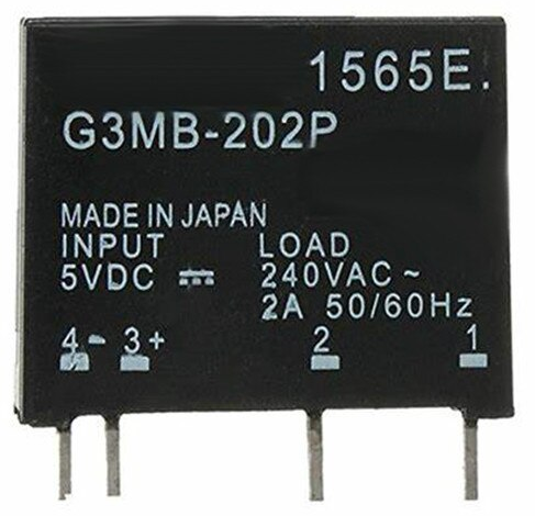
The G3MB-202P is a compact and reliable solid-state relay (SSR) designed for controlling high voltage and current loads using a low voltage control signal. It features an opto-isolated input for enhanced safety and electrical isolation, making it ideal for applications where electrical noise or interference is a concern. The G3MB-202P can switch AC loads up to 2A at 240VAC, making it suitable for a wide range of automation and control systems.

Explore Projects Built with G3MB-202P

Use Cirkit Designer to design, explore, and prototype these projects online. Some projects support real-time simulation. Click "Open Project" to start designing instantly!
ESP32-Based Smart Environmental Monitoring System with Relay Control
Image of SOCOTECO: A project utilizing G3MB-202P in a practical application
This is a smart environmental monitoring and control system featuring an ESP32 microcontroller interfaced with a PZEM004T for power monitoring, relay modules for actuating bulbs and a fan, and an LCD for user interface. It includes flame, gas, and vibration sensors for safety monitoring purposes.
Cirkit Designer LogoOpen Project in Cirkit Designer
Arduino Mega 2560 Based Security System with Fingerprint Authentication and SMS Alerts
Image of Door security system: A project utilizing G3MB-202P in a practical application
This circuit features an Arduino Mega 2560 microcontroller interfaced with a SIM800L GSM module, two fingerprint scanners, an I2C LCD display, an IR sensor, and a piezo buzzer. Power management is handled by a PowerBoost 1000 Basic Pad USB, a TP4056 charging module, and a Li-ion 18650 battery, with an option to use a Mini AC-DC 110V-230V to 5V 700mA module for direct power supply. The primary functionality appears to be a security system with GSM communication capabilities, biometric access control, and visual/audible feedback.
Cirkit Designer LogoOpen Project in Cirkit Designer
Battery-Powered Emergency Alert System with NUCLEO-F072RB, SIM800L, and GPS NEO 6M
Image of women safety: A project utilizing G3MB-202P in a practical application
This circuit is an emergency alert system that uses a NUCLEO-F072RB microcontroller to send SMS alerts and make calls via a SIM800L GSM module, while obtaining location data from a GPS NEO 6M module. The system is powered by a Li-ion battery and includes a TP4056 module for battery charging and protection, with a rocker switch to control power to the microcontroller.
Cirkit Designer LogoOpen Project in Cirkit Designer
ESP32-S3 GPS and Wind Speed Logger with Dual OLED Displays and CAN Bus
Image of esp32-s3-ellipse: A project utilizing G3MB-202P in a practical application
This circuit features an ESP32-S3 microcontroller interfaced with an SD card module, two OLED displays, a GPS module, and a CAN bus module. The ESP32-S3 records GPS data to the SD card, displays speed on one OLED, and shows wind speed from the CAN bus on the other OLED, providing a comprehensive data logging and display system.
Cirkit Designer LogoOpen Project in Cirkit Designer

Explore Projects Built with G3MB-202P

Use Cirkit Designer to design, explore, and prototype these projects online. Some projects support real-time simulation. Click "Open Project" to start designing instantly!
Image of SOCOTECO: A project utilizing G3MB-202P in a practical application
ESP32-Based Smart Environmental Monitoring System with Relay Control
This is a smart environmental monitoring and control system featuring an ESP32 microcontroller interfaced with a PZEM004T for power monitoring, relay modules for actuating bulbs and a fan, and an LCD for user interface. It includes flame, gas, and vibration sensors for safety monitoring purposes.
Cirkit Designer LogoOpen Project in Cirkit Designer
Image of Door security system: A project utilizing G3MB-202P in a practical application
Arduino Mega 2560 Based Security System with Fingerprint Authentication and SMS Alerts
This circuit features an Arduino Mega 2560 microcontroller interfaced with a SIM800L GSM module, two fingerprint scanners, an I2C LCD display, an IR sensor, and a piezo buzzer. Power management is handled by a PowerBoost 1000 Basic Pad USB, a TP4056 charging module, and a Li-ion 18650 battery, with an option to use a Mini AC-DC 110V-230V to 5V 700mA module for direct power supply. The primary functionality appears to be a security system with GSM communication capabilities, biometric access control, and visual/audible feedback.
Cirkit Designer LogoOpen Project in Cirkit Designer
Image of women safety: A project utilizing G3MB-202P in a practical application
Battery-Powered Emergency Alert System with NUCLEO-F072RB, SIM800L, and GPS NEO 6M
This circuit is an emergency alert system that uses a NUCLEO-F072RB microcontroller to send SMS alerts and make calls via a SIM800L GSM module, while obtaining location data from a GPS NEO 6M module. The system is powered by a Li-ion battery and includes a TP4056 module for battery charging and protection, with a rocker switch to control power to the microcontroller.
Cirkit Designer LogoOpen Project in Cirkit Designer
Image of esp32-s3-ellipse: A project utilizing G3MB-202P in a practical application
ESP32-S3 GPS and Wind Speed Logger with Dual OLED Displays and CAN Bus
This circuit features an ESP32-S3 microcontroller interfaced with an SD card module, two OLED displays, a GPS module, and a CAN bus module. The ESP32-S3 records GPS data to the SD card, displays speed on one OLED, and shows wind speed from the CAN bus on the other OLED, providing a comprehensive data logging and display system.
Cirkit Designer LogoOpen Project in Cirkit Designer

Common Applications and Use Cases

  • Home automation systems (e.g., controlling lights, fans, or appliances)
  • Industrial control systems
  • Microcontroller-based projects (e.g., Arduino, Raspberry Pi)
  • HVAC systems
  • Motor control and switching
  • Noise-sensitive environments requiring electrical isolation

Technical Specifications

Below are the key technical details of the G3MB-202P solid-state relay:

Parameter Value
Input Control Voltage 5V DC
Input Current 7.5mA (typical)
Output Voltage Range 75VAC to 264VAC
Maximum Output Current 2A
Isolation Voltage 2500V RMS
Switching Type Zero-cross switching
Operating Temperature -30°C to 80°C
Dimensions 25mm x 25mm x 8mm

Pin Configuration and Descriptions

The G3MB-202P has four pins, as described in the table below:

Pin Name Description
1 Input (+) Positive terminal for the control signal (typically 5V DC).
2 Input (-) Negative terminal for the control signal (ground).
3 Output (AC1) One terminal of the AC load to be controlled.
4 Output (AC2) The other terminal of the AC load to be controlled.

Usage Instructions

How to Use the G3MB-202P in a Circuit

  1. Connect the Control Signal:

    • Connect the positive control signal (e.g., from a microcontroller like Arduino) to the Input (+) pin.
    • Connect the ground of the control signal to the Input (-) pin.
  2. Connect the AC Load:

    • Connect one terminal of the AC load to the Output (AC1) pin.
    • Connect the other terminal of the AC load to the Output (AC2) pin.
  3. Power the Control Circuit:

    • Ensure the control signal voltage is within the specified range (5V DC).
  4. Switching the Load:

    • When the control signal is applied, the relay will switch the AC load on or off.

Important Considerations and Best Practices

  • Electrical Isolation: The opto-isolated input ensures safety, but always double-check connections to avoid short circuits.
  • Load Ratings: Do not exceed the maximum output current of 2A or the voltage range of 75VAC to 264VAC.
  • Heat Dissipation: Ensure proper ventilation or heat sinking if the relay is used near its maximum current rating.
  • Zero-Cross Switching: The relay uses zero-cross switching to minimize electrical noise and prolong the life of the load.

Example: Using the G3MB-202P with an Arduino UNO

Below is an example of how to control an AC load using the G3MB-202P and an Arduino UNO:

// Example: Controlling an AC load with G3MB-202P and Arduino UNO

const int relayPin = 7; // Pin connected to the G3MB-202P Input (+)

void setup() {
  pinMode(relayPin, OUTPUT); // Set the relay pin as an output
  digitalWrite(relayPin, LOW); // Ensure the relay is off at startup
}

void loop() {
  digitalWrite(relayPin, HIGH); // Turn the relay on (AC load ON)
  delay(5000); // Keep the load on for 5 seconds
  digitalWrite(relayPin, LOW); // Turn the relay off (AC load OFF)
  delay(5000); // Keep the load off for 5 seconds
}

Note: Always ensure proper safety precautions when working with high voltage AC loads. Disconnect power before making any changes to the circuit.

Troubleshooting and FAQs

Common Issues and Solutions

  1. The relay does not switch the load:

    • Verify that the control signal voltage is within the specified range (5V DC).
    • Check the wiring of the control signal and AC load.
    • Ensure the AC load is within the relay's rated voltage and current.
  2. The relay gets too hot:

    • Ensure the load current does not exceed 2A.
    • Provide adequate ventilation or use a heat sink if necessary.
  3. Electrical noise or interference:

    • Use proper grounding and shielding techniques in your circuit.
    • Ensure the relay is not placed near high-frequency noise sources.
  4. The relay switches erratically:

    • Check for stable and noise-free control signals.
    • Verify that the power supply to the control circuit is sufficient.

FAQs

Q: Can the G3MB-202P be used with a 3.3V control signal?
A: No, the G3MB-202P requires a 5V DC control signal for proper operation.

Q: Is the relay suitable for DC loads?
A: No, the G3MB-202P is designed for AC loads only and cannot switch DC loads.

Q: Can I use the relay to control inductive loads like motors?
A: Yes, but ensure the load is within the relay's rated current and voltage. For inductive loads, consider using a snubber circuit to protect the relay.

Q: Does the relay provide electrical isolation?
A: Yes, the opto-isolated input provides electrical isolation between the control and load circuits.