Cirkit Designer Logo
Cirkit Designer
Your all-in-one circuit design IDE
Home / 
Component Documentation

How to Use Adafruit DS2482S-800 8 Channel I2C to 1-Wire Bus Adapter: Examples, Pinouts, and Specs
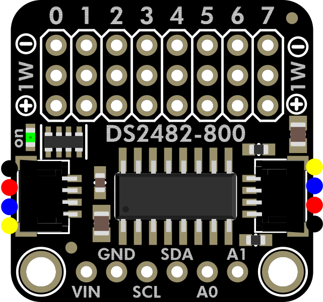

Image of Adafruit DS2482S-800 8 Channel I2C to 1-Wire Bus Adapter
Cirkit Designer LogoDesign with Adafruit DS2482S-800 8 Channel I2C to 1-Wire Bus Adapter in Cirkit Designer

Introduction

The Adafruit DS2482S-800 (Manufacturer Part ID: 6027) is a versatile 8-channel I2C to 1-Wire bus adapter designed to simplify communication between a microcontroller and multiple 1-Wire devices. This adapter enables seamless integration of up to 8 independent 1-Wire buses, making it ideal for applications requiring multiple sensors or devices on separate 1-Wire networks.

Explore Projects Built with Adafruit DS2482S-800 8 Channel I2C to 1-Wire Bus Adapter
Use Cirkit Designer to design, explore, and prototype these projects online. Some projects support real-time simulation. Click "Open Project" to start designing instantly!
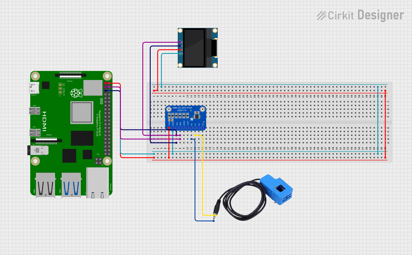
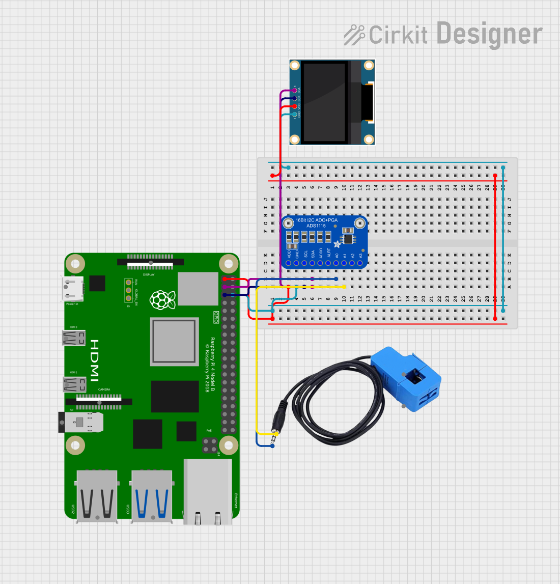
Raspberry Pi 4B-Based Current Monitoring System with I2C OLED Display
Image of Virtual Energy Monitoring Circuit: A project utilizing Adafruit DS2482S-800 8 Channel I2C to 1-Wire Bus Adapter in a practical application
This circuit features a Raspberry Pi 4B as the central processing unit, interfaced with an Adafruit ADS1115 16-bit I2C ADC for analog-to-digital conversion and a 0.96" OLED display for visual output. The ADS1115 is connected to a current sensor for measuring electrical current, with the sensor's output and burden pins connected to the ADC's analog input channels. The Raspberry Pi communicates with both the ADC and the OLED display over the I2C bus, using its GPIO2 and GPIO3 pins for data (SDA) and clock (SCL) lines, respectively.
Cirkit Designer LogoOpen Project in Cirkit Designer
Raspberry Pi 4B with I2C Current Sensing and OLED Display
Image of iot task 2: A project utilizing Adafruit DS2482S-800 8 Channel I2C to 1-Wire Bus Adapter in a practical application
This circuit features a Raspberry Pi 4B as the central processing unit, interfaced with an Adafruit ADS1115 16-bit I2C ADC for analog-to-digital conversion and a 0.96" OLED display for visual output. The ADC is connected to a current sensor for measuring electrical current, with the sensor's output connected to the ADC's AIN0 pin and the burden resistor connected to AIN1. The Raspberry Pi communicates with both the ADC and the OLED display over the I2C bus, using GPIO2 (SDA) and GPIO3 (SCL) for data exchange.
Cirkit Designer LogoOpen Project in Cirkit Designer
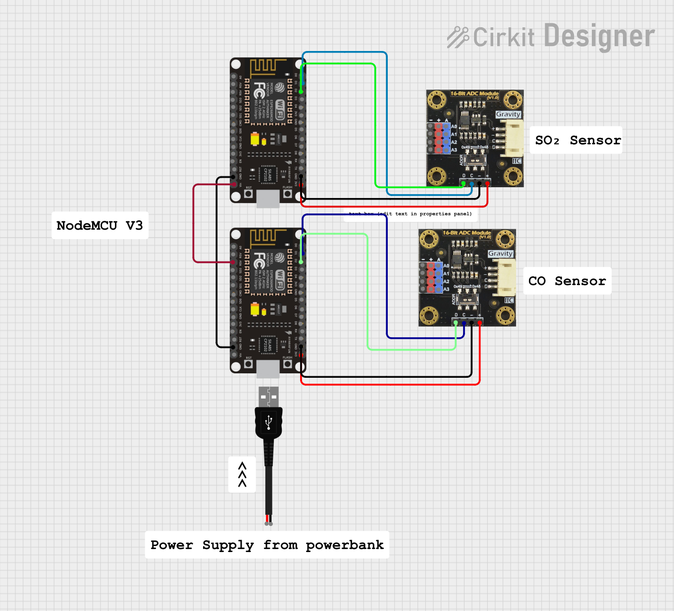
Wi-Fi Enabled Sensor Hub with ESP8266 and ADS1115 ADC
Image of Node Mcu Gas Sensor: A project utilizing Adafruit DS2482S-800 8 Channel I2C to 1-Wire Bus Adapter in a practical application
This circuit features two ESP8266 NodeMCU microcontrollers, each interfaced with a Gravity I2C ADS1115 16-Bit ADC module for analog-to-digital conversion. The microcontrollers communicate with the ADC modules via I2C protocol, with one set of connections for each microcontroller-ADC pair, and are powered through a common 3.3V and ground connection.
Cirkit Designer LogoOpen Project in Cirkit Designer
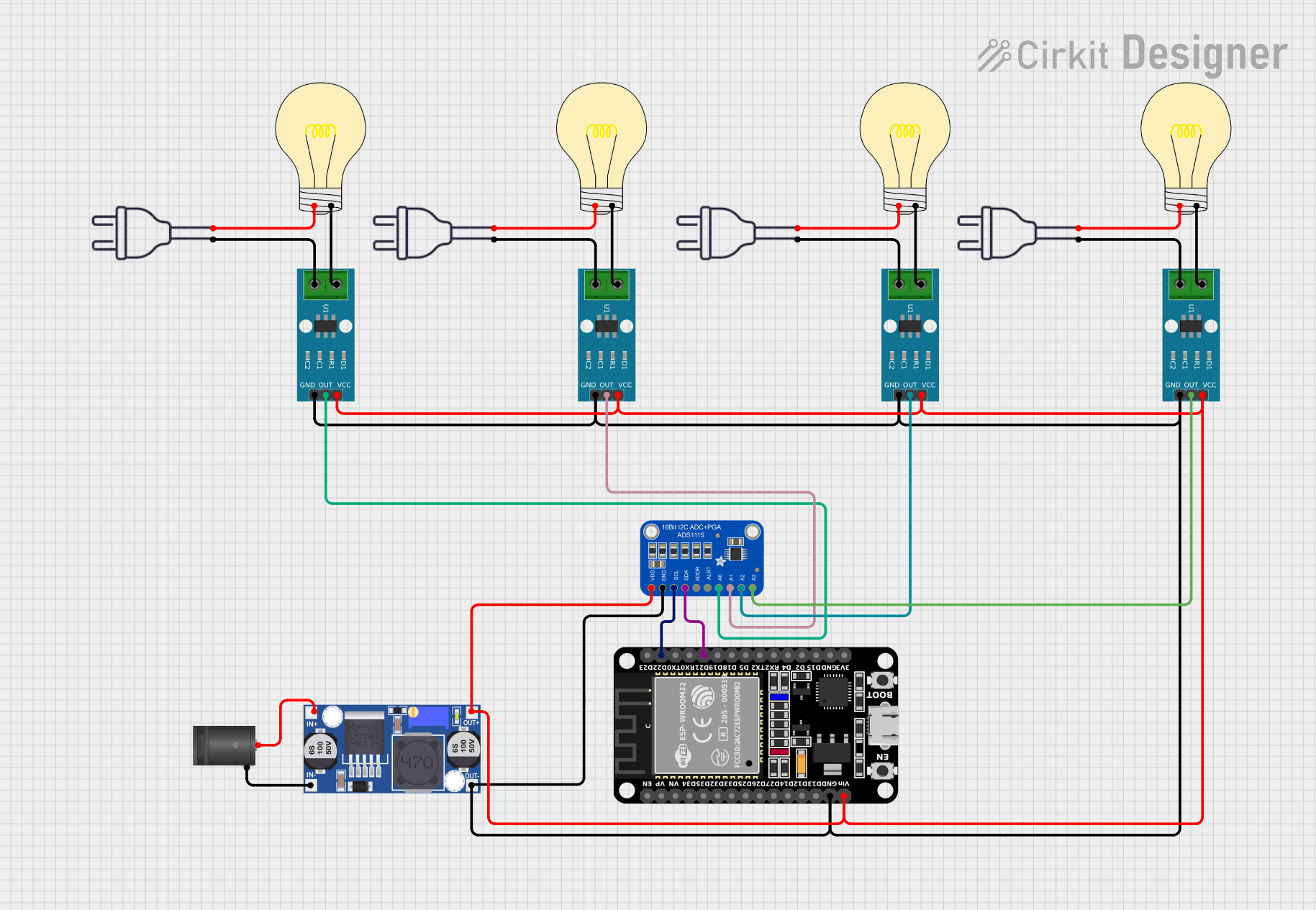
ESP32-Controlled Smart Lighting System with Power Monitoring
Image of Energy Monitoring System: A project utilizing Adafruit DS2482S-800 8 Channel I2C to 1-Wire Bus Adapter in a practical application
This circuit appears to be a multi-channel current monitoring system using several ACS712 current sensors to measure the current through different loads, likely bulbs connected to a 220V power source. The current readings from the sensors are digitized by an Adafruit ADS1115 16-bit ADC, which interfaces with an ESP32 microcontroller via I2C communication for further processing or telemetry. A buck converter is used to step down the voltage to power the ESP32 and the sensors, and the system is powered through a 2.1mm DC barrel jack, indicating it is designed for external power supply.
Cirkit Designer LogoOpen Project in Cirkit Designer

Explore Projects Built with Adafruit DS2482S-800 8 Channel I2C to 1-Wire Bus Adapter

Use Cirkit Designer to design, explore, and prototype these projects online. Some projects support real-time simulation. Click "Open Project" to start designing instantly!
Image of Virtual Energy Monitoring Circuit: A project utilizing Adafruit DS2482S-800 8 Channel I2C to 1-Wire Bus Adapter in a practical application
Raspberry Pi 4B-Based Current Monitoring System with I2C OLED Display
This circuit features a Raspberry Pi 4B as the central processing unit, interfaced with an Adafruit ADS1115 16-bit I2C ADC for analog-to-digital conversion and a 0.96" OLED display for visual output. The ADS1115 is connected to a current sensor for measuring electrical current, with the sensor's output and burden pins connected to the ADC's analog input channels. The Raspberry Pi communicates with both the ADC and the OLED display over the I2C bus, using its GPIO2 and GPIO3 pins for data (SDA) and clock (SCL) lines, respectively.
Cirkit Designer LogoOpen Project in Cirkit Designer
Image of iot task 2: A project utilizing Adafruit DS2482S-800 8 Channel I2C to 1-Wire Bus Adapter in a practical application
Raspberry Pi 4B with I2C Current Sensing and OLED Display
This circuit features a Raspberry Pi 4B as the central processing unit, interfaced with an Adafruit ADS1115 16-bit I2C ADC for analog-to-digital conversion and a 0.96" OLED display for visual output. The ADC is connected to a current sensor for measuring electrical current, with the sensor's output connected to the ADC's AIN0 pin and the burden resistor connected to AIN1. The Raspberry Pi communicates with both the ADC and the OLED display over the I2C bus, using GPIO2 (SDA) and GPIO3 (SCL) for data exchange.
Cirkit Designer LogoOpen Project in Cirkit Designer
Image of Node Mcu Gas Sensor: A project utilizing Adafruit DS2482S-800 8 Channel I2C to 1-Wire Bus Adapter in a practical application
Wi-Fi Enabled Sensor Hub with ESP8266 and ADS1115 ADC
This circuit features two ESP8266 NodeMCU microcontrollers, each interfaced with a Gravity I2C ADS1115 16-Bit ADC module for analog-to-digital conversion. The microcontrollers communicate with the ADC modules via I2C protocol, with one set of connections for each microcontroller-ADC pair, and are powered through a common 3.3V and ground connection.
Cirkit Designer LogoOpen Project in Cirkit Designer
Image of Energy Monitoring System: A project utilizing Adafruit DS2482S-800 8 Channel I2C to 1-Wire Bus Adapter in a practical application
ESP32-Controlled Smart Lighting System with Power Monitoring
This circuit appears to be a multi-channel current monitoring system using several ACS712 current sensors to measure the current through different loads, likely bulbs connected to a 220V power source. The current readings from the sensors are digitized by an Adafruit ADS1115 16-bit ADC, which interfaces with an ESP32 microcontroller via I2C communication for further processing or telemetry. A buck converter is used to step down the voltage to power the ESP32 and the sensors, and the system is powered through a 2.1mm DC barrel jack, indicating it is designed for external power supply.
Cirkit Designer LogoOpen Project in Cirkit Designer

Common Applications and Use Cases

  • Temperature Monitoring: Interfacing with multiple DS18B20 temperature sensors.
  • Industrial Automation: Managing multiple 1-Wire devices in factory environments.
  • Data Logging: Collecting data from distributed sensors.
  • Home Automation: Controlling and monitoring smart devices.
  • IoT Projects: Connecting multiple 1-Wire peripherals to a single microcontroller.

Technical Specifications

The following table outlines the key technical details of the Adafruit DS2482S-800:

Parameter Value
Operating Voltage 3.0V to 5.5V
Communication Protocol I2C
I2C Address Range 0x18 to 0x1F (configurable via A0, A1, A2)
1-Wire Channels 8 independent channels
Maximum 1-Wire Devices Up to 8 devices per channel (64 total)
Operating Temperature -40°C to +85°C
Package Type SOIC-16

Pin Configuration and Descriptions

The DS2482S-800 features 16 pins, as described in the table below:

Pin Number Pin Name Description
1 SDA I2C Data Line
2 SCL I2C Clock Line
3 A0 I2C Address Selection Bit 0
4 A1 I2C Address Selection Bit 1
5 A2 I2C Address Selection Bit 2
6 GND Ground
7 1W0 1-Wire Channel 0
8 1W1 1-Wire Channel 1
9 1W2 1-Wire Channel 2
10 1W3 1-Wire Channel 3
11 1W4 1-Wire Channel 4
12 1W5 1-Wire Channel 5
13 1W6 1-Wire Channel 6
14 1W7 1-Wire Channel 7
15 VDD Power Supply (3.0V to 5.5V)
16 RSTZ Reset (Active Low)

Usage Instructions

How to Use the Component in a Circuit

  1. Power the Adapter: Connect the VDD pin to a 3.3V or 5V power source and the GND pin to ground.
  2. Connect I2C Lines: Attach the SDA and SCL pins to the corresponding I2C pins on your microcontroller.
  3. Set the I2C Address: Configure the A0, A1, and A2 pins to set the I2C address (default is 0x18).
  4. Connect 1-Wire Devices: Attach up to 8 1-Wire devices to the 1W0–1W7 pins. Each pin supports multiple devices if required.
  5. Pull-Up Resistors: Add appropriate pull-up resistors (typically 4.7kΩ) to each 1-Wire channel to ensure proper communication.

Important Considerations and Best Practices

  • I2C Pull-Up Resistors: Ensure that the I2C bus has pull-up resistors (typically 4.7kΩ) on the SDA and SCL lines.
  • 1-Wire Bus Length: Keep the 1-Wire bus length as short as possible to minimize signal degradation.
  • Power Supply: Use a stable power supply to avoid communication errors.
  • Reset Pin: Connect the RSTZ pin to the microcontroller or pull it high if not used.

Example Code for Arduino UNO

Below is an example of how to use the DS2482S-800 with an Arduino UNO to read data from a DS18B20 temperature sensor connected to channel 0:

#include <Wire.h>
#include <OneWire.h>
#include <DS2482.h>

// Initialize DS2482 object
DS2482 ds2482;

// 1-Wire bus on channel 0
OneWire oneWire(0);

void setup() {
  Serial.begin(9600);
  Wire.begin(); // Initialize I2C communication

  // Initialize DS2482
  if (!ds2482.begin()) {
    Serial.println("DS2482 initialization failed!");
    while (1); // Halt if initialization fails
  }

  Serial.println("DS2482 initialized successfully.");
}

void loop() {
  byte addr[8];

  // Search for 1-Wire devices on channel 0
  if (oneWire.search(addr)) {
    Serial.print("Device found: ");
    for (byte i = 0; i < 8; i++) {
      Serial.print(addr[i], HEX);
      Serial.print(" ");
    }
    Serial.println();
  } else {
    Serial.println("No devices found on channel 0.");
    oneWire.reset_search(); // Reset search for next iteration
  }

  delay(1000); // Wait 1 second before next scan
}

Troubleshooting and FAQs

Common Issues and Solutions

  1. No Response from the Adapter:

    • Ensure the I2C address is correctly configured and matches the code.
    • Verify that the SDA and SCL lines are properly connected and have pull-up resistors.
  2. 1-Wire Devices Not Detected:

    • Check the pull-up resistors on the 1-Wire channels.
    • Ensure the 1-Wire devices are properly connected and powered.
  3. Communication Errors:

    • Verify the power supply voltage is within the specified range (3.0V to 5.5V).
    • Check for noise or interference on the I2C or 1-Wire lines.

FAQs

Q: Can I connect multiple DS2482S-800 adapters to the same I2C bus?
A: Yes, you can connect up to 8 adapters by configuring unique I2C addresses using the A0, A1, and A2 pins.

Q: What is the maximum cable length for the 1-Wire bus?
A: The maximum length depends on the number of devices and the environment, but typically it should not exceed 30 meters.

Q: Do I need external pull-up resistors for the 1-Wire channels?
A: Yes, each 1-Wire channel requires a pull-up resistor (typically 4.7kΩ) for proper operation.