How to Use ESP32 Development Board ESP-WROOM-32: Examples, Pinouts, and Specs
Introduction
The ESP32 Development Board ESP-WROOM-32 is a powerful and versatile microcontroller board designed for a wide range of applications. It features built-in Wi-Fi and Bluetooth capabilities, making it an excellent choice for Internet of Things (IoT) projects, prototyping, and embedded systems development. With its dual-core processor, ample GPIO pins, and support for various communication protocols, the ESP32 is a favorite among hobbyists and professionals alike.
Explore Projects Built with ESP32 Development Board ESP-WROOM-32


Explore Projects Built with ESP32 Development Board ESP-WROOM-32
Common Applications and Use Cases
- IoT devices and smart home automation
- Wireless sensor networks
- Wearable technology
- Robotics and automation systems
- Prototyping and educational projects
- Data logging and remote monitoring
Technical Specifications
Key Technical Details
- Microcontroller: Tensilica Xtensa LX6 dual-core processor
- Clock Speed: Up to 240 MHz
- Flash Memory: 4 MB (varies by model)
- SRAM: 520 KB
- Wi-Fi: 802.11 b/g/n
- Bluetooth: v4.2 BR/EDR and BLE
- Operating Voltage: 3.3V
- Input Voltage: 5V (via USB) or 7-12V (via VIN pin)
- GPIO Pins: 36 (multipurpose, including ADC, DAC, PWM, I2C, SPI, UART)
- ADC Channels: 18 (12-bit resolution)
- DAC Channels: 2
- Power Consumption: Ultra-low power consumption in deep sleep mode (~10 µA)
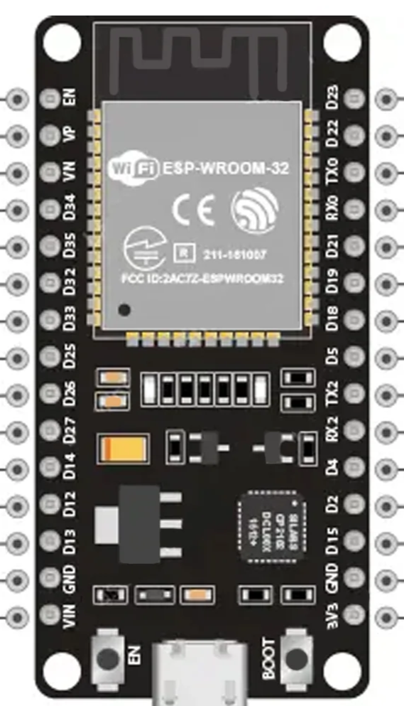
Pin Configuration and Descriptions
The ESP32 Development Board ESP-WROOM-32 has a total of 38 pins. Below is a table summarizing the key pin functions:
| Pin | Name | Description |
|---|---|---|
| 1-3 | GND | Ground pins for power and signal reference. |
| 4 | 3V3 | 3.3V output pin for powering external components. |
| 5 | VIN | Input voltage pin (7-12V) for powering the board. |
| 6-11 | GPIO0-GPIO5 | General-purpose input/output pins. Can be configured for ADC, PWM, etc. |
| 12-13 | GPIO12-GPIO13 | General-purpose pins. GPIO12 is often used for boot mode selection. |
| 14-15 | GPIO14-GPIO15 | General-purpose pins. GPIO15 can be used for PWM or SPI communication. |
| 16-17 | TXD0, RXD0 | UART0 transmit (TX) and receive (RX) pins for serial communication. |
| 18-19 | SDA, SCL | I2C data (SDA) and clock (SCL) pins. |
| 20-21 | MOSI, MISO | SPI Master Out Slave In (MOSI) and Master In Slave Out (MISO) pins. |
| 22 | EN | Enable pin. Pulling this pin low resets the board. |
| 23-24 | ADC1, ADC2 | Analog-to-digital converter channels. |
| 25-26 | DAC1, DAC2 | Digital-to-analog converter channels. |
| 27-36 | GPIO16-GPIO39 | Additional GPIO pins with various functionalities (ADC, touch, etc.). |
Note: Some GPIO pins have specific restrictions or are used during boot. Refer to the ESP32 datasheet for detailed pin behavior.
Usage Instructions
How to Use the ESP32 in a Circuit
Powering the Board:
- Use a micro-USB cable to power the board via the USB port (5V input).
- Alternatively, supply 7-12V to the VIN pin or 3.3V to the 3V3 pin.
Connecting Peripherals:
- Use the GPIO pins to connect sensors, actuators, or other peripherals.
- Ensure that the voltage levels of connected devices are compatible with the ESP32 (3.3V logic).
Programming the Board:
- Install the Arduino IDE or ESP-IDF (Espressif IoT Development Framework).
- Add the ESP32 board support package to the Arduino IDE.
- Connect the board to your computer via USB and select the correct COM port.
Uploading Code:
- Write your code in the Arduino IDE or ESP-IDF.
- Click the upload button to flash the code to the ESP32.
Important Considerations and Best Practices
- Avoid using GPIO6-GPIO11 for general-purpose tasks, as these are connected to the onboard flash memory.
- Use level shifters when interfacing with 5V devices to prevent damage to the ESP32.
- For low-power applications, utilize the deep sleep mode to conserve energy.
- Ensure proper grounding and decoupling capacitors for stable operation in noisy environments.
Example Code for Arduino IDE
The following example demonstrates how to blink an LED connected to GPIO2:
// Define the GPIO pin for the LED
const int ledPin = 2;

void setup() {
  // Set the LED pin as an output
  pinMode(ledPin, OUTPUT);
}

void loop() {
  // Turn the LED on
  digitalWrite(ledPin, HIGH);
  delay(1000); // Wait for 1 second

  // Turn the LED off
  digitalWrite(ledPin, LOW);
  delay(1000); // Wait for 1 second
}
Tip: Ensure the LED is connected to GPIO2 with a current-limiting resistor (e.g., 220Ω).
Troubleshooting and FAQs
Common Issues and Solutions
The board is not detected by the computer:
- Ensure the USB cable is functional and supports data transfer.
- Install the correct USB-to-serial driver (e.g., CP2102 or CH340).
Code upload fails:
- Check that the correct COM port and board type are selected in the Arduino IDE.
- Press and hold the "BOOT" button on the ESP32 while uploading the code.
Wi-Fi connection issues:
- Verify the SSID and password in your code.
- Ensure the router is within range and supports 2.4 GHz Wi-Fi.
GPIO pin not working as expected:
- Check if the pin is reserved for specific functions (e.g., flash memory).
- Ensure the pin is not being used by another peripheral or library.
FAQs
Q: Can the ESP32 operate on battery power?
A: Yes, the ESP32 can be powered by a LiPo battery connected to the VIN pin. Use a voltage regulator if needed.Q: How do I reset the ESP32?
A: Press the "EN" button on the board to reset it.Q: Can I use the ESP32 with 5V logic devices?
A: No, the ESP32 operates on 3.3V logic. Use level shifters for compatibility with 5V devices.Q: How do I reduce power consumption?
A: Use the deep sleep mode and disable unused peripherals to minimize power usage.
This documentation provides a comprehensive guide to using the ESP32 Development Board ESP-WROOM-32 effectively. For more advanced features, refer to the official Espressif documentation.