How to Use L298N Motor Driver H-Bridge (Motor Driver): Examples, Pinouts, and Specs
L298N Motor Driver H-Bridge Documentation
1. Introduction
The L298N Motor Driver H-Bridge, manufactured by STMicroelectronics (Part ID: L298N), is a robust and versatile dual H-Bridge motor driver. It is designed to control the direction and speed of DC motors and stepper motors, making it an essential component in robotics, automation, and motor control applications. The L298N can drive two motors simultaneously, supporting bidirectional control and pulse-width modulation (PWM) for speed regulation.
Common Applications:
- Robotics (e.g., controlling robot wheels)
- Conveyor belt systems
- Automated gates and doors
- CNC machines and 3D printers
- DIY motorized projects
- Stepper motor control in precision systems
2. Technical Specifications
The L298N is a high-power motor driver capable of handling significant current and voltage levels. Below are its key specifications and pin configuration details.
Key Technical Details:
| Parameter | Value |
|---|---|
| Operating Voltage | 5V to 46V |
| Output Current (per channel) | 2A (continuous), 3A (peak) |
| Logic Voltage | 5V |
| Power Dissipation | 25W (with proper heat sinking) |
| Control Logic Levels | High: 2.3V to 5V, Low: 0V to 1.5V |
| Number of Channels | 2 (dual H-Bridge) |
| PWM Frequency | Up to 20 kHz |
| Operating Temperature Range | -25°C to +130°C |
Pin Configuration and Descriptions:
The L298N module typically includes additional components like a voltage regulator and terminal blocks for easy wiring. Below is the pinout for the L298N IC and its corresponding module.
L298N IC Pinout:
| Pin | Name | Description |
|---|---|---|
| 1 | Enable A | Enables/Disables Motor A (High = Enabled, Low = Disabled) |
| 2 | Input 1 | Logic input to control Motor A direction (works with Input 2) |
| 3 | Input 2 | Logic input to control Motor A direction (works with Input 1) |
| 4 | Output 1 | Motor A output terminal 1 |
| 5 | Output 2 | Motor A output terminal 2 |
| 6 | VSS (Logic) | Logic voltage supply (5V) |
| 7 | Ground | Common ground |
| 8 | VS (Motor) | Motor power supply (up to 46V) |
| 9 | Output 3 | Motor B output terminal 1 |
| 10 | Output 4 | Motor B output terminal 2 |
| 11 | Input 3 | Logic input to control Motor B direction (works with Input 4) |
| 12 | Input 4 | Logic input to control Motor B direction (works with Input 3) |
| 13 | Enable B | Enables/Disables Motor B (High = Enabled, Low = Disabled) |
| 14 | Ground | Common ground |
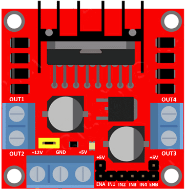
L298N Module Pinout:
| Pin | Description |
|---|---|
| ENA | Enable pin for Motor A (connect to PWM for speed control) |
| IN1, IN2 | Control pins for Motor A direction |
| OUT1, OUT2 | Output terminals for Motor A |
| ENB | Enable pin for Motor B (connect to PWM for speed control) |
| IN3, IN4 | Control pins for Motor B direction |
| OUT3, OUT4 | Output terminals for Motor B |
| 12V (VS) | Motor power supply (up to 46V) |
| 5V | Logic voltage supply (can be used to power external logic circuits) |
| GND | Common ground |
3. Usage Instructions
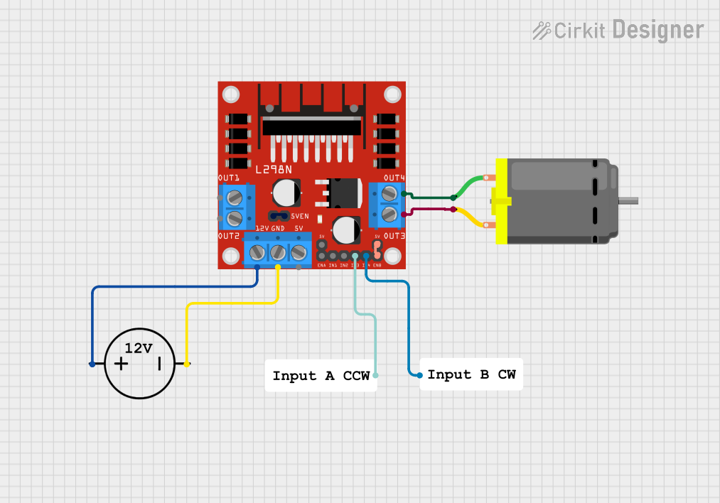
Connecting the L298N to a Circuit:
Power Supply:
- Connect the motor power supply (up to 46V) to the
12V(VS) pin. - Connect the logic power supply (5V) to the
5Vpin. - Ensure all grounds (GND) are connected to a common ground.
- Connect the motor power supply (up to 46V) to the
Motor Connections:
- Connect the motor terminals to
OUT1andOUT2for Motor A, andOUT3andOUT4for Motor B.
- Connect the motor terminals to
Control Pins:
- Use
IN1andIN2to control the direction of Motor A. - Use
IN3andIN4to control the direction of Motor B. - Use
ENAandENBfor enabling/disabling motors or for speed control via PWM.
- Use
Direction Control Logic:
- Set
IN1HIGH andIN2LOW to rotate Motor A in one direction. - Set
IN1LOW andIN2HIGH to rotate Motor A in the opposite direction. - Similarly, use
IN3andIN4for Motor B.
- Set
Speed Control:
- Connect a PWM signal to
ENA(for Motor A) orENB(for Motor B) to control speed.
- Connect a PWM signal to
Important Considerations:
- Use a heat sink or cooling fan for high-current applications to prevent overheating.
- Ensure the motor power supply voltage matches the motor's rated voltage.
- Avoid exceeding the maximum current rating to prevent damage to the IC.
4. Example Arduino Code
Below is an example of how to control two DC motors using the L298N and an Arduino UNO.
// Define motor control pins
#define ENA 9  // PWM pin for Motor A speed control
#define IN1 8  // Motor A direction control pin 1
#define IN2 7  // Motor A direction control pin 2
#define ENB 10 // PWM pin for Motor B speed control
#define IN3 6  // Motor B direction control pin 1
#define IN4 5  // Motor B direction control pin 2

void setup() {
  // Set motor control pins as outputs
  pinMode(ENA, OUTPUT);
  pinMode(IN1, OUTPUT);
  pinMode(IN2, OUTPUT);
  pinMode(ENB, OUTPUT);
  pinMode(IN3, OUTPUT);
  pinMode(IN4, OUTPUT);
}

void loop() {
  // Motor A: Forward at 50% speed
  digitalWrite(IN1, HIGH);  // Set IN1 HIGH
  digitalWrite(IN2, LOW);   // Set IN2 LOW
  analogWrite(ENA, 128);    // Set ENA to 50% duty cycle (128/255)

  // Motor B: Reverse at 75% speed
  digitalWrite(IN3, LOW);   // Set IN3 LOW
  digitalWrite(IN4, HIGH);  // Set IN4 HIGH
  analogWrite(ENB, 192);    // Set ENB to 75% duty cycle (192/255)

  delay(2000); // Run motors for 2 seconds

  // Stop both motors
  analogWrite(ENA, 0);      // Set ENA to 0% duty cycle (stop Motor A)
  analogWrite(ENB, 0);      // Set ENB to 0% duty cycle (stop Motor B)

  delay(2000); // Wait for 2 seconds
}
5. Troubleshooting and FAQs
Common Issues and Solutions:
Motors Not Running:
- Ensure the power supply is connected and providing sufficient voltage.
- Verify that the
ENAandENBpins are set HIGH or receiving a PWM signal.
Overheating:
- Use a heat sink or cooling fan for high-current applications.
- Check for short circuits or excessive current draw from the motors.
Erratic Motor Behavior:
- Ensure all ground connections are properly connected.
- Verify the logic control signals are correct and stable.
No Speed Control:
- Confirm that the PWM signal is being sent to the
ENAorENBpins. - Check the Arduino code for errors in the
analogWrite()function.
- Confirm that the PWM signal is being sent to the
FAQs:
Q1: Can the L298N drive stepper motors?
Yes, the L298N can drive bipolar stepper motors by controlling the two H-Bridge channels.
Q2: Can I power the Arduino from the L298N module?
Yes, if the module has a 5V regulator, you can use the 5V pin to power the Arduino. Ensure the motor power supply is at least 7V.
Q3: What is the maximum PWM frequency supported?
The L298N supports PWM frequencies up to 20 kHz.
This documentation provides a comprehensive guide to using the L298N Motor Driver H-Bridge. For further details, refer to the official
Explore Projects Built with L298N Motor Driver H-Bridge (Motor Driver)
Explore Projects Built with L298N Motor Driver H-Bridge (Motor Driver)