Cirkit Designer
Your all-in-one circuit design IDE
Home /
Component Documentation
How to Use AITrip ADXL335 GY-61: Examples, Pinouts, and Specs
Introduction
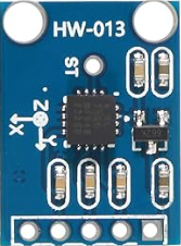
The AITrip ADXL335 GY-61 is a small, thin, low-power, complete 3-axis accelerometer with signal-conditioned voltage outputs. It measures acceleration with a minimum full-scale range of ±3g. It can measure both dynamic acceleration (e.g., vibration) and static acceleration (e.g., gravity).
Explore Projects Built with AITrip ADXL335 GY-61
ADXL335 Accelerometer Data Visualization with Oscilloscope

This circuit connects an AITrip ADXL335 GY-61 accelerometer to an oscilloscope for signal visualization and a 3xAA battery pack for power. The accelerometer's Z-axis output is directly monitored on the oscilloscope, allowing for real-time observation of acceleration changes along that axis. The circuit is likely used for educational or testing purposes to demonstrate how the accelerometer responds to motion.
Arduino Nano-Based Wireless Motion Detection System with ADXL335 Accelerometer and NRF24L01 Transceiver
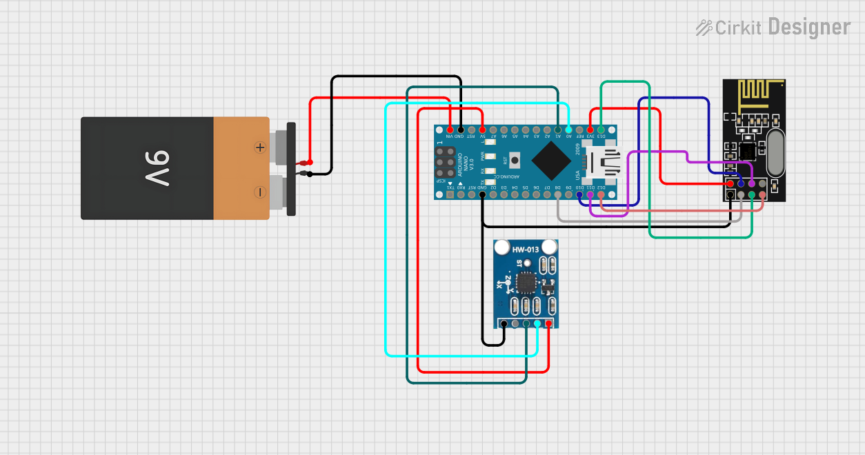
This circuit features an Arduino Nano interfaced with an ADXL335 accelerometer and an NRF24L01 wireless communication module. The Arduino is powered by a 9V battery and reads the X and Y-axis outputs from the accelerometer, potentially to transmit this data wirelessly via the NRF24L01. The NRF24L01 is connected to the Arduino's SPI pins for communication and its VCC is connected to the Arduino's 3.3V output.
Arduino UNO and ADXL345 Accelerometer Data Logger
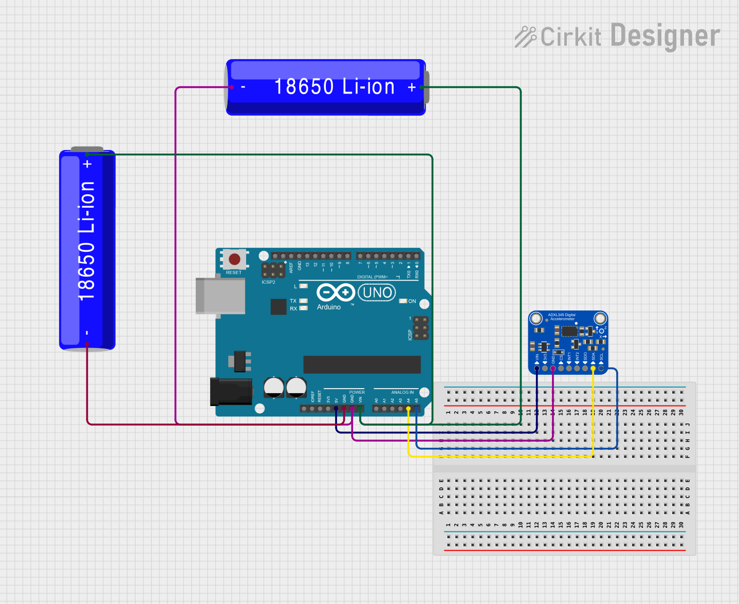
This circuit features an Arduino UNO microcontroller interfaced with an Adafruit ADXL345 accelerometer for motion detection, powered by two parallel-connected 18650 Li-ion batteries. The accelerometer communicates with the Arduino over I2C, and the system is designed for further code development to utilize the motion sensing capabilities.
Arduino UNO-Based Impact Detection and GPS Tracking System with GSM Communication
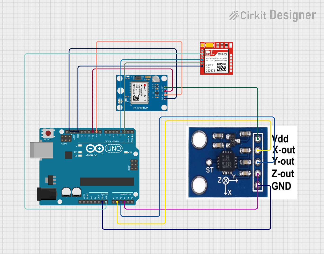
This circuit features an Arduino UNO interfaced with an ADXXL335 accelerometer, a Neo 6M GPS module, and a Sim800l GSM module. The Arduino collects acceleration data and GPS coordinates, and can send SMS alerts or make calls via the GSM module in case of a detected impact or upon receiving a specific SMS command. The system is designed for applications such as vehicle tracking and accident detection.
Explore Projects Built with AITrip ADXL335 GY-61
ADXL335 Accelerometer Data Visualization with Oscilloscope
This circuit connects an AITrip ADXL335 GY-61 accelerometer to an oscilloscope for signal visualization and a 3xAA battery pack for power. The accelerometer's Z-axis output is directly monitored on the oscilloscope, allowing for real-time observation of acceleration changes along that axis. The circuit is likely used for educational or testing purposes to demonstrate how the accelerometer responds to motion.
Arduino Nano-Based Wireless Motion Detection System with ADXL335 Accelerometer and NRF24L01 Transceiver
This circuit features an Arduino Nano interfaced with an ADXL335 accelerometer and an NRF24L01 wireless communication module. The Arduino is powered by a 9V battery and reads the X and Y-axis outputs from the accelerometer, potentially to transmit this data wirelessly via the NRF24L01. The NRF24L01 is connected to the Arduino's SPI pins for communication and its VCC is connected to the Arduino's 3.3V output.
Arduino UNO and ADXL345 Accelerometer Data Logger
This circuit features an Arduino UNO microcontroller interfaced with an Adafruit ADXL345 accelerometer for motion detection, powered by two parallel-connected 18650 Li-ion batteries. The accelerometer communicates with the Arduino over I2C, and the system is designed for further code development to utilize the motion sensing capabilities.
Arduino UNO-Based Impact Detection and GPS Tracking System with GSM Communication
This circuit features an Arduino UNO interfaced with an ADXXL335 accelerometer, a Neo 6M GPS module, and a Sim800l GSM module. The Arduino collects acceleration data and GPS coordinates, and can send SMS alerts or make calls via the GSM module in case of a detected impact or upon receiving a specific SMS command. The system is designed for applications such as vehicle tracking and accident detection.
Common Applications and Use Cases
- Tilt sensing in handheld devices
- Motion detection in security systems
- Vibration monitoring in industrial equipment
- Activity monitoring in wearable electronics
- Game controller input
Technical Specifications
Key Technical Details
- Power Supply: 1.8V - 3.6V DC
- Sensitivity: Typically 300 mV/g at 3V
- Measurement Range: ±3g
- Bandwidth: 0.5 Hz to 1600 Hz
- Operating Temperature: -40°C to +85°C
Pin Configuration and Descriptions
| Pin Number | Name | Description |
|---|---|---|
| 1 | VCC | Power supply (1.8V - 3.6V DC) |
| 2 | X-OUT | Analog voltage output for X-axis |
| 3 | Y-OUT | Analog voltage output for Y-axis |
| 4 | Z-OUT | Analog voltage output for Z-axis |
| 5 | GND | Ground |
Usage Instructions
How to Use the Component in a Circuit
- Connect the VCC pin to a power supply within the range of 1.8V to 3.6V.
- Connect the GND pin to the ground of the power supply.
- Connect the X-OUT, Y-OUT, and Z-OUT pins to the analog input pins of a microcontroller, such as an Arduino UNO, to read the acceleration values.
Important Considerations and Best Practices
- Ensure that the power supply voltage does not exceed 3.6V to prevent damage.
- Use capacitors for noise reduction if the application is sensitive to noise.
- Calibrate the sensor for accurate measurements by determining the zero-g offset and sensitivity.
- Avoid physical shock and vibration during operation as it may affect the readings.
Example Code for Arduino UNO
// Include the Arduino core library
#include <Arduino.h>

// Define the analog pins connected to the accelerometer
const int xPin = A0;
const int yPin = A1;
const int zPin = A2;

void setup() {
  // Initialize serial communication at 9600 baud rate
  Serial.begin(9600);
}

void loop() {
  // Read the raw values from the accelerometer
  int xRaw = analogRead(xPin);
  int yRaw = analogRead(yPin);
  int zRaw = analogRead(zPin);

  // Convert the raw values to 'g' values
  float xG = (xRaw - 338.0) / 100.0; // Replace 338.0 with your calibrated zero-g value
  float yG = (yRaw - 338.0) / 100.0; // Replace 338.0 with your calibrated zero-g value
  float zG = (zRaw - 338.0) / 100.0; // Replace 338.0 with your calibrated zero-g value

  // Print the acceleration 'g' values to the Serial Monitor
  Serial.print("X: ");
  Serial.print(xG);
  Serial.print("g, Y: ");
  Serial.print(yG);
  Serial.print("g, Z: ");
  Serial.print(zG);
  Serial.println("g");

  // Delay for a bit to avoid spamming the Serial Monitor
  delay(100);
}
Code Comments
- The
analogReadfunction is used to read the voltage output from the accelerometer. - The raw values are then converted to 'g' values using calibration data.
- The
Serial.printstatements output the acceleration values to the Serial Monitor. - The
delayfunction is used to slow down the loop for readability.
Troubleshooting and FAQs
Common Issues Users Might Face
- Inaccurate Readings: Ensure that the sensor is properly calibrated. Check for any mechanical stress or temperature variations that might affect the sensor.
- No Readings: Verify that the sensor is correctly powered and that all connections are secure. Check the microcontroller's analog pins for proper functionality.
Solutions and Tips for Troubleshooting
- Calibration: Perform a calibration routine at startup to account for zero-g offset and sensitivity.
- Connection Issues: Use a multimeter to check for continuity and correct voltage levels at the sensor's pins.
- Code Debugging: Add serial print statements to debug the code and ensure that the sensor values are being read correctly.
FAQs
Q: Can the ADXL335 measure rotation?
- A: No, the ADXL335 is an accelerometer and can only measure linear acceleration.
Q: What is the sensitivity of the sensor?
- A: The sensitivity is typically 300 mV/g at 3V supply voltage.
Q: How do I convert the analog readings to 'g' values?
- A: You need to subtract the zero-g offset from the raw reading and then divide by the sensitivity.
Remember to always handle electronic components with care and follow proper ESD safety procedures.