Cirkit Designer Logo
Cirkit Designer
Your all-in-one circuit design IDE
Home / 
Component Documentation

How to Use Ethernet Switch: Examples, Pinouts, and Specs

Image of Ethernet Switch
Cirkit Designer LogoDesign with Ethernet Switch in Cirkit Designer

Introduction

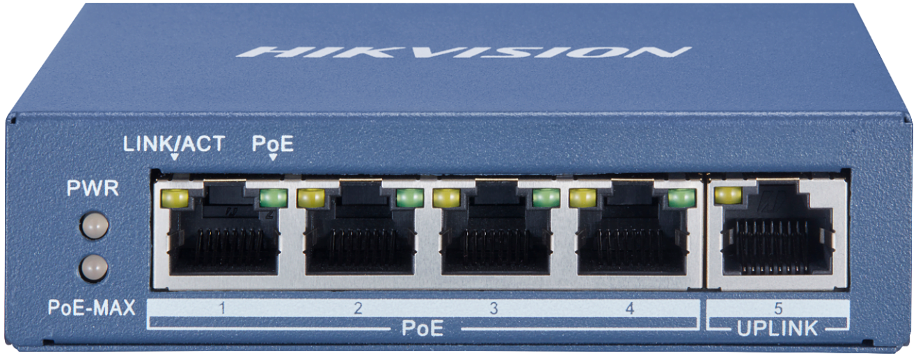
The Hikvision DS-3E0505P-E is an Ethernet switch designed to facilitate the connection of multiple devices within a Local Area Network (LAN). It operates by using MAC addresses to forward data packets to their intended recipients, which enhances the efficiency and security of the network. This switch is commonly used in small office/home office (SOHO) environments, as well as in larger enterprise settings where multiple devices such as computers, printers, and storage servers need to be interconnected.

Explore Projects Built with Ethernet Switch

Use Cirkit Designer to design, explore, and prototype these projects online. Some projects support real-time simulation. Click "Open Project" to start designing instantly!
ESP32 and W5500 Ethernet Module Controlled 8-Channel Relay
Image of ESP32 38Pin 8 Channel Relay USB-C: A project utilizing Ethernet Switch in a practical application
This circuit enables Ethernet connectivity and device control through an ESP32 microcontroller. It uses the W5500 Ethernet module for network communication and controls an 8-channel relay module for switching external devices or loads.
Cirkit Designer LogoOpen Project in Cirkit Designer
Optiplex Micro and PoE Camera Surveillance System with Ethernet Switching
Image of Engine Mounts Wiring: A project utilizing Ethernet Switch in a practical application
This circuit describes a networked system where an Optiplex Micro computer is powered by a PC Power Supply and connected to a PC Screen via HDMI for display output. The computer is networked through an Ethernet Switch, which also connects to two PoE Cameras and a Toyopuc PLC. The Ethernet Switch is powered by a PoE PSU 48V DC, and all AC-powered devices are connected to a common 220V AC source.
Cirkit Designer LogoOpen Project in Cirkit Designer
ESP8266 NodeMCU with LoRa and RS-485 Communication and Ethernet Connectivity
Image of Wiring Diagram LoRa: A project utilizing Ethernet Switch in a practical application
This circuit serves as a multi-protocol communication hub featuring two ESP8266 NodeMCUs for processing, each connected to a LoRa Ra-02 SX1278 for long-range wireless communication. One NodeMCU is also connected to an RS-485 module for serial communication and a W5500 Ethernet module for network connectivity, with MB102 modules supplying power.
Cirkit Designer LogoOpen Project in Cirkit Designer
Wi-Fi Controlled Relay Module with ESP8266 and MCP23017
Image of smart home: A project utilizing Ethernet Switch in a practical application
This circuit is a WiFi-enabled relay control system using an ESP8266-01 module and an MCP23017 I/O expander. The ESP8266 communicates with the MCP23017 via I2C to control an 8-channel relay module based on the state of 8 rocker switches, allowing for remote and manual control of connected devices.
Cirkit Designer LogoOpen Project in Cirkit Designer

Explore Projects Built with Ethernet Switch

Use Cirkit Designer to design, explore, and prototype these projects online. Some projects support real-time simulation. Click "Open Project" to start designing instantly!
Image of ESP32 38Pin 8 Channel Relay USB-C: A project utilizing Ethernet Switch in a practical application
ESP32 and W5500 Ethernet Module Controlled 8-Channel Relay
This circuit enables Ethernet connectivity and device control through an ESP32 microcontroller. It uses the W5500 Ethernet module for network communication and controls an 8-channel relay module for switching external devices or loads.
Cirkit Designer LogoOpen Project in Cirkit Designer
Image of Engine Mounts Wiring: A project utilizing Ethernet Switch in a practical application
Optiplex Micro and PoE Camera Surveillance System with Ethernet Switching
This circuit describes a networked system where an Optiplex Micro computer is powered by a PC Power Supply and connected to a PC Screen via HDMI for display output. The computer is networked through an Ethernet Switch, which also connects to two PoE Cameras and a Toyopuc PLC. The Ethernet Switch is powered by a PoE PSU 48V DC, and all AC-powered devices are connected to a common 220V AC source.
Cirkit Designer LogoOpen Project in Cirkit Designer
Image of Wiring Diagram LoRa: A project utilizing Ethernet Switch in a practical application
ESP8266 NodeMCU with LoRa and RS-485 Communication and Ethernet Connectivity
This circuit serves as a multi-protocol communication hub featuring two ESP8266 NodeMCUs for processing, each connected to a LoRa Ra-02 SX1278 for long-range wireless communication. One NodeMCU is also connected to an RS-485 module for serial communication and a W5500 Ethernet module for network connectivity, with MB102 modules supplying power.
Cirkit Designer LogoOpen Project in Cirkit Designer
Image of smart home: A project utilizing Ethernet Switch in a practical application
Wi-Fi Controlled Relay Module with ESP8266 and MCP23017
This circuit is a WiFi-enabled relay control system using an ESP8266-01 module and an MCP23017 I/O expander. The ESP8266 communicates with the MCP23017 via I2C to control an 8-channel relay module based on the state of 8 rocker switches, allowing for remote and manual control of connected devices.
Cirkit Designer LogoOpen Project in Cirkit Designer

Common Applications and Use Cases

  • Small to medium-sized business networks
  • Home networks
  • IP surveillance systems
  • Networked storage solutions
  • VoIP phone systems

Technical Specifications

Key Technical Details

  • Standards and Protocols: IEEE 802.3, IEEE 802.3u, IEEE 802.3x
  • Interface: 5 x 10/100Mbps Auto-Negotiation RJ45 ports (Auto MDI/MDIX)
  • Network Media:
    • 10BASE-T: UTP category 3, 4, 5 cable (maximum 100m)
    • 100BASE-TX: UTP category 5, 5e cable (maximum 100m)
  • Fan Quantity: Fanless
  • Power Supply: External Power Adapter(Output: 48VDC / 1.25A)
  • Power Consumption: Maximum: 63W (with PoE)
  • PoE Ports (RJ45): Standard: 802.3 af compliant
  • PoE Power Budget: 35W
  • Mac Address Table: 2K
  • Dimension: 100 × 98 × 25 mm
  • Max Power for Single Port: 15.4W

Pin Configuration and Descriptions

Port Number Description PoE Support Data Speeds
1 Data In/Out, PoE Yes 10/100Mbps
2 Data In/Out, PoE Yes 10/100Mbps
3 Data In/Out, PoE Yes 10/100Mbps
4 Data In/Out, PoE Yes 10/100Mbps
5 Data In/Out (Uplink Port) No 10/100Mbps

Usage Instructions

How to Use the Component in a Circuit

  1. Connecting Devices: Connect Ethernet cables from the devices you wish to network into the RJ45 ports on the switch. Ports 1-4 support Power over Ethernet (PoE), which can power compatible devices.
  2. Powering the Switch: Connect the external power adapter to the switch and plug it into an AC outlet.
  3. Network Configuration: The switch does not require any software configuration for basic operation. It is a plug-and-play device that will begin switching packets between connected devices upon power-up.

Important Considerations and Best Practices

  • Cable Quality: Use high-quality, category 5e or above Ethernet cables to ensure optimal performance.
  • PoE Devices: Ensure that any device you connect to the PoE ports is PoE-compliant. The switch can supply up to 15.4W per port, with a total PoE budget of 35W.
  • Ventilation: Keep the switch in a well-ventilated area to prevent overheating, as it is fanless.
  • Surge Protection: Use surge protectors to safeguard the switch and connected devices against power surges.

Troubleshooting and FAQs

Common Issues

  • No Power: Ensure the power adapter is connected properly and the outlet is functioning.
  • No Connectivity: Check if the Ethernet cables are firmly plugged into the ports. Test with different cables if necessary.
  • Slow Performance: Verify that the cables are not damaged and are of the correct category for the desired speeds.

Solutions and Tips for Troubleshooting

  • LED Indicators: Use the LED indicators on the switch to diagnose connectivity and activity.
  • Restart the Switch: Unplug the power adapter, wait for a minute, and plug it back in to reset the switch.
  • Check for Overloading: Ensure the total power consumption of PoE devices does not exceed the switch's PoE power budget.

FAQs

Q: Can I use this switch to power non-PoE devices? A: Yes, non-PoE devices can be connected to the switch without any issues. They will simply not receive power over Ethernet.

Q: What is the maximum distance I can have between the switch and connected devices? A: The maximum cable length for Ethernet (Cat 5e and above) is 100 meters (328 feet).

Q: Does this switch support gigabit speeds? A: No, the DS-3E0505P-E supports speeds up to 100Mbps per port.

Q: Can I daisy-chain multiple switches? A: Yes, you can connect multiple switches together by using one of the ports to link them. However, be mindful of potential network bottlenecks and the increased risk of network loops.

Note: This documentation is for informational purposes only and is based on the specifications provided for the Hikvision DS-3E0505P-E Ethernet switch. Always consult the manufacturer's official documentation for the most accurate and detailed information.