Cirkit Designer Logo
Cirkit Designer
Your all-in-one circuit design IDE
Home / 
Component Documentation

How to Use ESP32-S3-DevKitC-1-N32R16V Entwicklungsplatine: Examples, Pinouts, and Specs

Image of ESP32-S3-DevKitC-1-N32R16V Entwicklungsplatine
Cirkit Designer LogoDesign with ESP32-S3-DevKitC-1-N32R16V Entwicklungsplatine in Cirkit Designer

Introduction

The ESP32-S3-DevKitC-1-N32R16V Entwicklungsplatine is a development board manufactured by Espressif. It is built around the ESP32-S3 microcontroller, which features dual-core Xtensa LX7 processors, integrated Wi-Fi (802.11 b/g/n), and Bluetooth 5 (LE) capabilities. This board is designed for IoT applications, offering high performance, low power consumption, and advanced connectivity options. It is ideal for prototyping, development, and deployment of smart devices.

Explore Projects Built with ESP32-S3-DevKitC-1-N32R16V Entwicklungsplatine

Use Cirkit Designer to design, explore, and prototype these projects online. Some projects support real-time simulation. Click "Open Project" to start designing instantly!
ESP32-Based GPS Tracker with SD Card Logging and Barometric Sensor
Image of gps projekt circuit: A project utilizing ESP32-S3-DevKitC-1-N32R16V Entwicklungsplatine in a practical application
This circuit features an ESP32 Wroom Dev Kit as the main microcontroller, interfaced with an MPL3115A2 sensor for pressure and temperature readings, and a Neo 6M GPS module for location tracking. The ESP32 is also connected to an SD card reader for data logging purposes. A voltage regulator is used to step down the USB power supply to 3.3V, which powers the ESP32, the sensor, and the SD card reader.
Cirkit Designer LogoOpen Project in Cirkit Designer
ESP32-Based Smart Agriculture System with LoRa Communication
Image of Soil Monitoring Device: A project utilizing ESP32-S3-DevKitC-1-N32R16V Entwicklungsplatine in a practical application
This circuit features an ESP32 Devkit V1 microcontroller as the central processing unit, interfacing with various sensors including a PH Meter, an NPK Soil Sensor, and a Soil Moisture Sensor for environmental data collection. It also includes an EBYTE LoRa E220 module for wireless communication. Power management is handled by a Step Up Boost Power Converter, which is connected to a 12V Battery, stepping up the voltage to power the ESP32 and sensors, with common ground connections throughout the circuit.
Cirkit Designer LogoOpen Project in Cirkit Designer
ESP32 and Logic Level Converter-Based Wi-Fi Controlled Interface
Image of Toshiba AC ESP32 devkit v1: A project utilizing ESP32-S3-DevKitC-1-N32R16V Entwicklungsplatine in a practical application
This circuit features an ESP32 Devkit V1 microcontroller connected to a Bi-Directional Logic Level Converter, which facilitates voltage level shifting between the ESP32 and external components. The ESP32 is powered through its VIN pin via an alligator clip cable, and the logic level converter is connected to various pins on the ESP32 to manage different voltage levels for communication.
Cirkit Designer LogoOpen Project in Cirkit Designer
ESP32-S3 GPS and Wind Speed Logger with Dual OLED Displays and CAN Bus
Image of esp32-s3-ellipse: A project utilizing ESP32-S3-DevKitC-1-N32R16V Entwicklungsplatine in a practical application
This circuit features an ESP32-S3 microcontroller interfaced with an SD card module, two OLED displays, a GPS module, and a CAN bus module. The ESP32-S3 records GPS data to the SD card, displays speed on one OLED, and shows wind speed from the CAN bus on the other OLED, providing a comprehensive data logging and display system.
Cirkit Designer LogoOpen Project in Cirkit Designer

Explore Projects Built with ESP32-S3-DevKitC-1-N32R16V Entwicklungsplatine

Use Cirkit Designer to design, explore, and prototype these projects online. Some projects support real-time simulation. Click "Open Project" to start designing instantly!
Image of gps projekt circuit: A project utilizing ESP32-S3-DevKitC-1-N32R16V Entwicklungsplatine in a practical application
ESP32-Based GPS Tracker with SD Card Logging and Barometric Sensor
This circuit features an ESP32 Wroom Dev Kit as the main microcontroller, interfaced with an MPL3115A2 sensor for pressure and temperature readings, and a Neo 6M GPS module for location tracking. The ESP32 is also connected to an SD card reader for data logging purposes. A voltage regulator is used to step down the USB power supply to 3.3V, which powers the ESP32, the sensor, and the SD card reader.
Cirkit Designer LogoOpen Project in Cirkit Designer
Image of Soil Monitoring Device: A project utilizing ESP32-S3-DevKitC-1-N32R16V Entwicklungsplatine in a practical application
ESP32-Based Smart Agriculture System with LoRa Communication
This circuit features an ESP32 Devkit V1 microcontroller as the central processing unit, interfacing with various sensors including a PH Meter, an NPK Soil Sensor, and a Soil Moisture Sensor for environmental data collection. It also includes an EBYTE LoRa E220 module for wireless communication. Power management is handled by a Step Up Boost Power Converter, which is connected to a 12V Battery, stepping up the voltage to power the ESP32 and sensors, with common ground connections throughout the circuit.
Cirkit Designer LogoOpen Project in Cirkit Designer
Image of Toshiba AC ESP32 devkit v1: A project utilizing ESP32-S3-DevKitC-1-N32R16V Entwicklungsplatine in a practical application
ESP32 and Logic Level Converter-Based Wi-Fi Controlled Interface
This circuit features an ESP32 Devkit V1 microcontroller connected to a Bi-Directional Logic Level Converter, which facilitates voltage level shifting between the ESP32 and external components. The ESP32 is powered through its VIN pin via an alligator clip cable, and the logic level converter is connected to various pins on the ESP32 to manage different voltage levels for communication.
Cirkit Designer LogoOpen Project in Cirkit Designer
Image of esp32-s3-ellipse: A project utilizing ESP32-S3-DevKitC-1-N32R16V Entwicklungsplatine in a practical application
ESP32-S3 GPS and Wind Speed Logger with Dual OLED Displays and CAN Bus
This circuit features an ESP32-S3 microcontroller interfaced with an SD card module, two OLED displays, a GPS module, and a CAN bus module. The ESP32-S3 records GPS data to the SD card, displays speed on one OLED, and shows wind speed from the CAN bus on the other OLED, providing a comprehensive data logging and display system.
Cirkit Designer LogoOpen Project in Cirkit Designer

Common Applications and Use Cases

  • IoT devices and smart home systems
  • Wearable electronics
  • Industrial automation and control
  • Wireless sensor networks
  • Voice recognition and AI-based applications
  • Prototyping for Wi-Fi and Bluetooth-enabled devices

Technical Specifications

Below are the key technical details of the ESP32-S3-DevKitC-1-N32R16V:

Specification Details
Microcontroller ESP32-S3 (Xtensa LX7 dual-core, 240 MHz)
Flash Memory 16 MB (Octal SPI Flash)
PSRAM 8 MB
Wi-Fi 802.11 b/g/n (2.4 GHz)
Bluetooth Bluetooth 5 (LE)
GPIO Pins 27 GPIOs (configurable for various functions)
Operating Voltage 3.3V
Input Voltage Range 5V (via USB Type-C)
Interfaces SPI, I2C, I2S, UART, PWM, ADC, DAC, USB OTG
USB Connectivity USB Type-C (supports programming and power supply)
Dimensions 54 mm x 25.5 mm
Operating Temperature -40°C to +85°C
Power Consumption Ultra-low power modes available

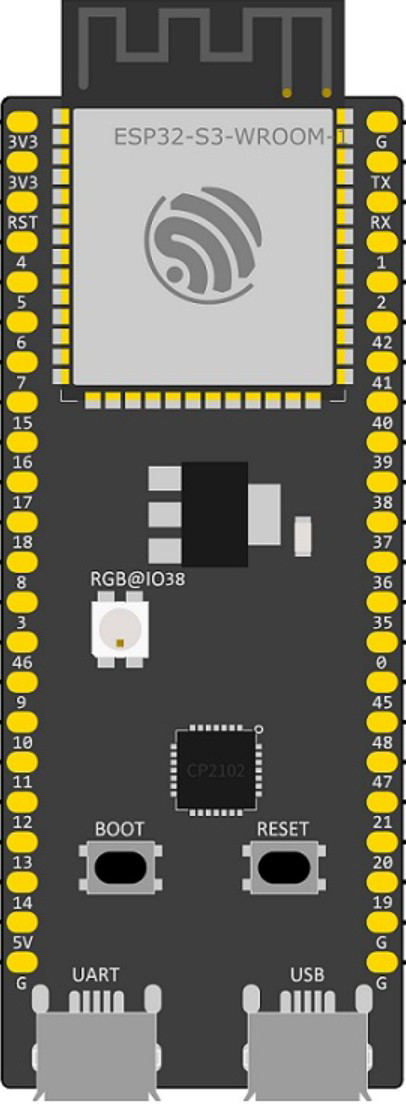
Pin Configuration and Descriptions

The ESP32-S3-DevKitC-1-N32R16V features a 2x19 pin header layout. Below is a summary of the pin configuration:

Pin Name Description
1 3V3 3.3V power output
2 GND Ground
3 IO0 GPIO0, used for boot mode selection
4 IO1 GPIO1, general-purpose input/output
5 IO2 GPIO2, supports ADC, PWM, and other functions
6 IO3 GPIO3, supports ADC, PWM, and other functions
... ... ... (Refer to the official datasheet for the full pinout)
38 EN Enable pin, used to reset the board

Note: For the complete pinout and alternate functions, refer to the official Espressif documentation.

Usage Instructions

How to Use the Component in a Circuit

  1. Powering the Board:

    • Connect the board to your computer or power source using a USB Type-C cable. The board operates at 3.3V internally but accepts 5V input via USB.
  2. Programming the Board:

    • Install the Espressif ESP32-S3 board package in the Arduino IDE or use the ESP-IDF (Espressif IoT Development Framework) for advanced development.
    • Select the correct board and port in the IDE, then upload your code.
  3. Connecting Peripherals:

    • Use the GPIO pins to connect sensors, actuators, or other peripherals. Ensure that the voltage levels are compatible (3.3V logic).
  4. Wi-Fi and Bluetooth Setup:

    • Use the built-in libraries (e.g., WiFi.h and BluetoothSerial.h in Arduino) to configure wireless connectivity.

Important Considerations and Best Practices

  • Voltage Levels: Ensure all connected peripherals operate at 3.3V logic to avoid damaging the board.
  • Boot Mode: To enter bootloader mode, hold the BOOT button while pressing the EN button.
  • Power Supply: Use a stable 5V power source when powering the board via USB.
  • ESD Protection: Handle the board with care to avoid electrostatic discharge damage.

Example Code for Arduino UNO Integration

Below is an example of how to use the ESP32-S3-DevKitC-1-N32R16V to connect to Wi-Fi and send data to a server:

#include <WiFi.h>

// Replace with your network credentials
const char* ssid = "Your_SSID";
const char* password = "Your_PASSWORD";

void setup() {
  Serial.begin(115200); // Initialize serial communication at 115200 baud
  delay(1000);

  // Connect to Wi-Fi
  Serial.println("Connecting to Wi-Fi...");
  WiFi.begin(ssid, password);

  while (WiFi.status() != WL_CONNECTED) {
    delay(500);
    Serial.print(".");
  }

  Serial.println("\nWi-Fi connected!");
  Serial.print("IP Address: ");
  Serial.println(WiFi.localIP()); // Print the device's IP address
}

void loop() {
  // Add your main code here
}

Note: Replace Your_SSID and Your_PASSWORD with your Wi-Fi credentials.

Troubleshooting and FAQs

Common Issues Users Might Face

  1. Board Not Detected by Computer:

    • Ensure the USB cable is functional and supports data transfer.
    • Verify that the correct drivers for the ESP32-S3 are installed.
  2. Upload Fails in Arduino IDE:

    • Check that the correct board and port are selected in the IDE.
    • Hold the BOOT button while uploading the code to force the board into bootloader mode.
  3. Wi-Fi Connection Issues:

    • Verify that the SSID and password are correct.
    • Ensure the Wi-Fi network operates on the 2.4 GHz band (not 5 GHz).
  4. Peripherals Not Working:

    • Double-check the wiring and ensure the peripherals are compatible with 3.3V logic.
    • Confirm that the correct GPIO pins are used in the code.

Solutions and Tips for Troubleshooting

  • Use the Serial Monitor in the Arduino IDE to debug and view error messages.
  • Refer to the official Espressif documentation for advanced debugging techniques.
  • If the board becomes unresponsive, press the EN button to reset it.

For further assistance, visit the Espressif Support Forum.