How to Use Smart 4Ch Relay Switch 10A + Shell | RF433Mhz + BT | DC or AC In | WiFi Tuya Smart Life: Examples, Pinouts, and Specs
Introduction
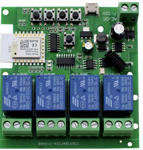
The Smart 4Ch Relay Switch (Model: TYWD 4ch-RF) is a versatile electronic component designed for controlling up to four independent channels. It supports both DC and AC inputs, making it suitable for a wide range of applications. With built-in RF433MHz, Bluetooth, and WiFi connectivity, this relay switch can be remotely controlled via the Tuya Smart Life app, enabling seamless integration into smart home or industrial automation systems.
Explore Projects Built with Smart 4Ch Relay Switch 10A + Shell | RF433Mhz + BT | DC or AC In | WiFi Tuya Smart Life
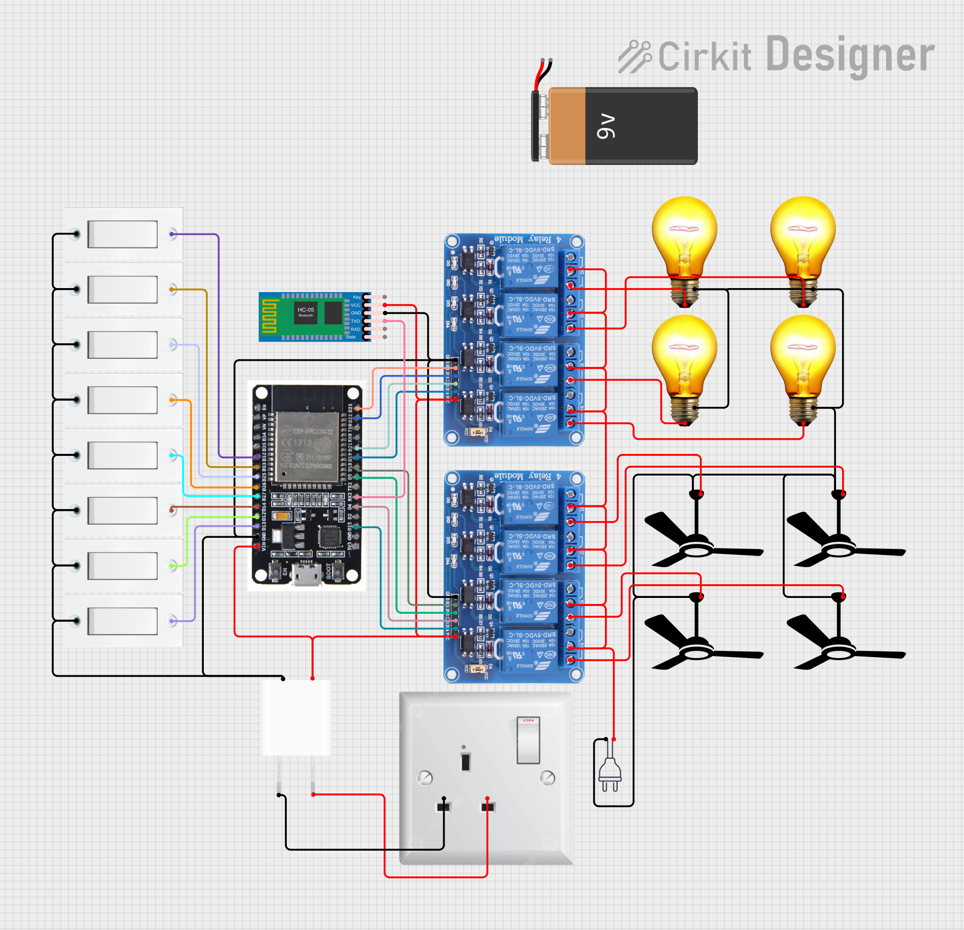
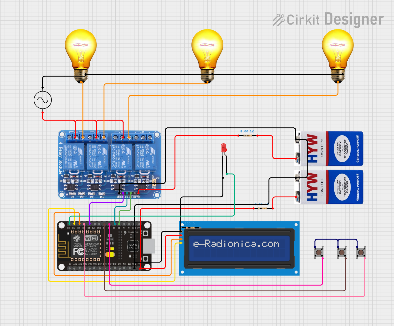
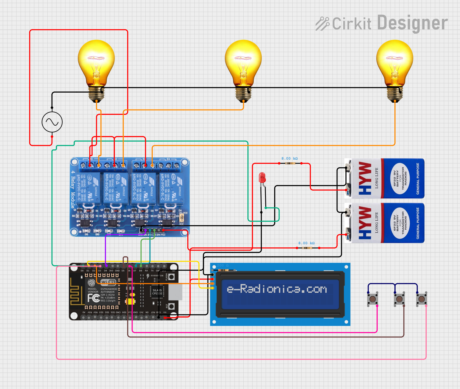
Explore Projects Built with Smart 4Ch Relay Switch 10A + Shell | RF433Mhz + BT | DC or AC In | WiFi Tuya Smart Life
Common Applications
- Smart Home Automation: Control lights, fans, or other appliances remotely.
- Industrial Automation: Manage machinery or equipment with multi-channel control.
- IoT Projects: Integrate with IoT platforms for advanced automation.
- Remote Control Systems: Use RF433MHz or Bluetooth for local control without WiFi.
Technical Specifications
Key Technical Details
| Parameter | Specification |
|---|---|
| Manufacturer | Tuya |
| Model Number | TYWD 4ch-RF |
| Input Voltage Range | DC: 5V-24V / AC: 85V-250V |
| Maximum Load Current | 10A per channel |
| Connectivity | RF433MHz, Bluetooth, WiFi (Tuya Smart Life app) |
| Number of Channels | 4 |
| Operating Temperature | -10°C to 60°C |
| Dimensions | 145mm x 90mm x 40mm |
| Shell Material | ABS Plastic (Fireproof) |
| Certifications | CE, FCC, RoHS |
Pin Configuration and Descriptions
The relay switch has a terminal block for input power and output connections. Below is the pin configuration:
Input Power Terminals
| Pin Name | Description |
|---|---|
| L | Live wire for AC input |
| N | Neutral wire for AC input |
| DC+ | Positive terminal for DC input |
| DC- | Negative terminal for DC input |
Output Terminals (Per Channel)
| Pin Name | Description |
|---|---|
| NO | Normally Open terminal |
| COM | Common terminal |
| NC | Normally Closed terminal |
Control Interface
| Pin Name | Description |
|---|---|
| RF433MHz | RF signal receiver for remote control |
| BT | Bluetooth module for local control |
| WiFi | WiFi module for Tuya Smart Life app |
Usage Instructions
How to Use the Component in a Circuit
Power the Relay Switch:
- For DC input, connect the positive wire to
DC+and the negative wire toDC-. - For AC input, connect the live wire to
Land the neutral wire toN.
- For DC input, connect the positive wire to
Connect the Load:
- For each channel, connect the load to the
COMandNOterminals if you want the circuit to be normally open (default off). - Use the
COMandNCterminals if you want the circuit to be normally closed (default on).
- For each channel, connect the load to the
Control the Relay:
- Use the Tuya Smart Life app to configure and control the relay via WiFi.
- Alternatively, use an RF433MHz remote or Bluetooth for local control.
Integrate with IoT Platforms:
- The relay can be linked to IoT platforms like Google Home or Amazon Alexa for voice control.
Important Considerations and Best Practices
- Ensure the input voltage matches the relay's specifications (DC: 5V-24V or AC: 85V-250V).
- Do not exceed the maximum load current of 10A per channel.
- Use proper insulation and fireproof enclosures for safety.
- Place the relay in a well-ventilated area to prevent overheating.
- For RF433MHz control, ensure the remote is within the specified range (typically 20-30 meters).
Arduino UNO Integration Example
The relay can be controlled using an Arduino UNO via its GPIO pins. Below is an example code to control one of the relay channels:
// Example: Controlling a single channel of the Smart 4Ch Relay Switch
// Connect the relay's input pin (e.g., CH1) to Arduino pin 7.

#define RELAY_PIN 7  // Define the GPIO pin connected to the relay

void setup() {
  pinMode(RELAY_PIN, OUTPUT);  // Set the relay pin as an output
  digitalWrite(RELAY_PIN, LOW);  // Initialize the relay to OFF state
}

void loop() {
  digitalWrite(RELAY_PIN, HIGH);  // Turn the relay ON
  delay(5000);  // Keep it ON for 5 seconds
  digitalWrite(RELAY_PIN, LOW);  // Turn the relay OFF
  delay(5000);  // Keep it OFF for 5 seconds
}
Note: Use a transistor or optocoupler if the relay requires more current than the Arduino pin can supply.
Troubleshooting and FAQs
Common Issues and Solutions
Relay Not Responding to Commands:
- Ensure the relay is powered correctly and the input voltage is within the specified range.
- Check the WiFi, Bluetooth, or RF433MHz connection status.
WiFi Connection Fails:
- Verify that the relay is in pairing mode (LED indicator should blink rapidly).
- Ensure the WiFi network is 2.4GHz (not 5GHz).
Load Not Switching:
- Confirm the load is connected to the correct terminals (
COMandNOorCOMandNC). - Check if the load exceeds the maximum current rating (10A per channel).
- Confirm the load is connected to the correct terminals (
Overheating:
- Ensure the relay is not operating near its maximum load for extended periods.
- Place the relay in a well-ventilated area.
FAQs
Q1: Can I control the relay without WiFi?
Yes, you can use the RF433MHz remote or Bluetooth for local control.
Q2: Is the relay compatible with voice assistants?
Yes, it can be integrated with Google Home or Amazon Alexa via the Tuya Smart Life app.
Q3: Can I use the relay for both AC and DC loads simultaneously?
Yes, but ensure proper isolation and do not exceed the maximum current rating per channel.
Q4: What is the range of RF433MHz control?
The typical range is 20-30 meters, depending on environmental factors.
Q5: How do I reset the relay?
Press and hold the reset button for 5 seconds until the LED indicator blinks rapidly.