How to Use ardino uno r3: Examples, Pinouts, and Specs
Introduction
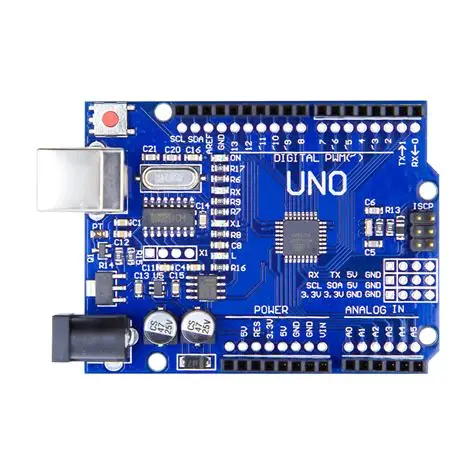
The Arduino Uno R3 is a microcontroller board based on the ATmega328P. It is widely used in prototyping, embedded systems, and educational projects due to its simplicity and versatility. The board features 14 digital input/output pins (6 of which can be used as PWM outputs), 6 analog inputs, a USB connection for programming, a power jack, and a reset button. Its open-source design and extensive community support make it an excellent choice for beginners and experienced developers alike.
Explore Projects Built with ardino uno r3
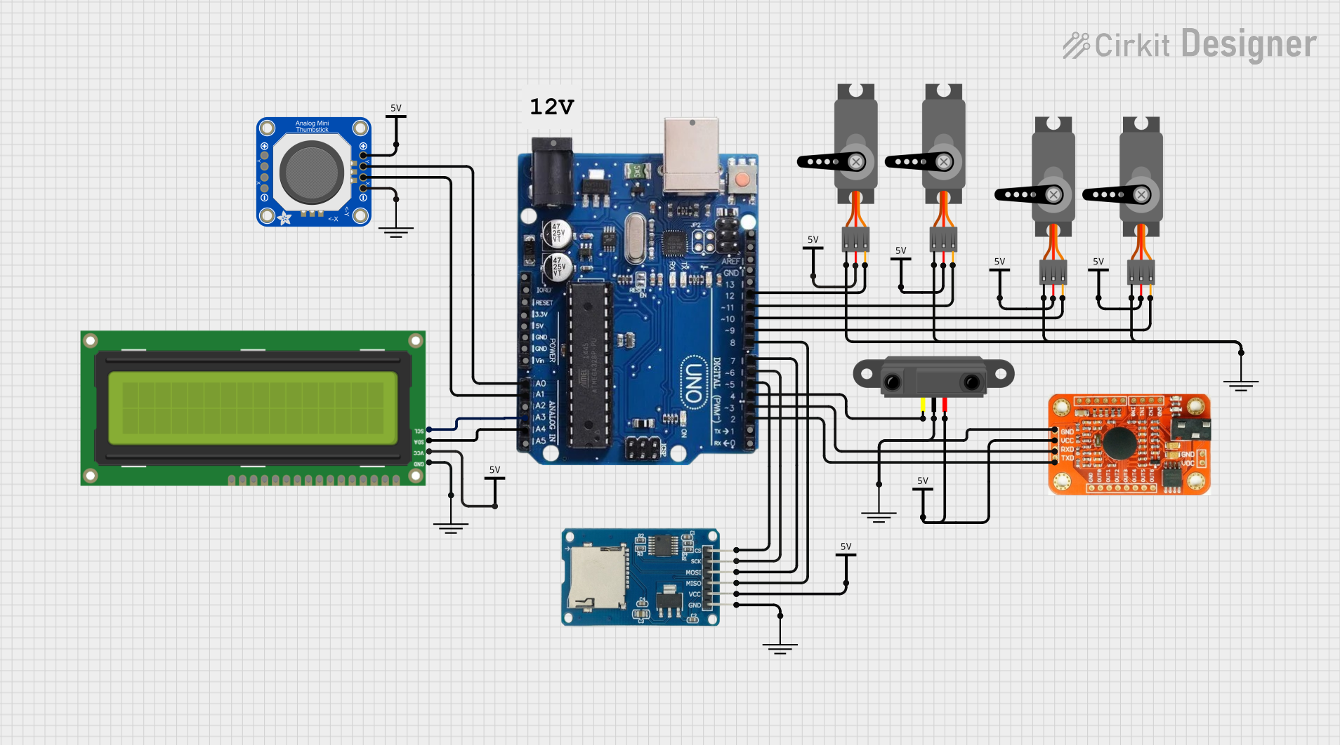
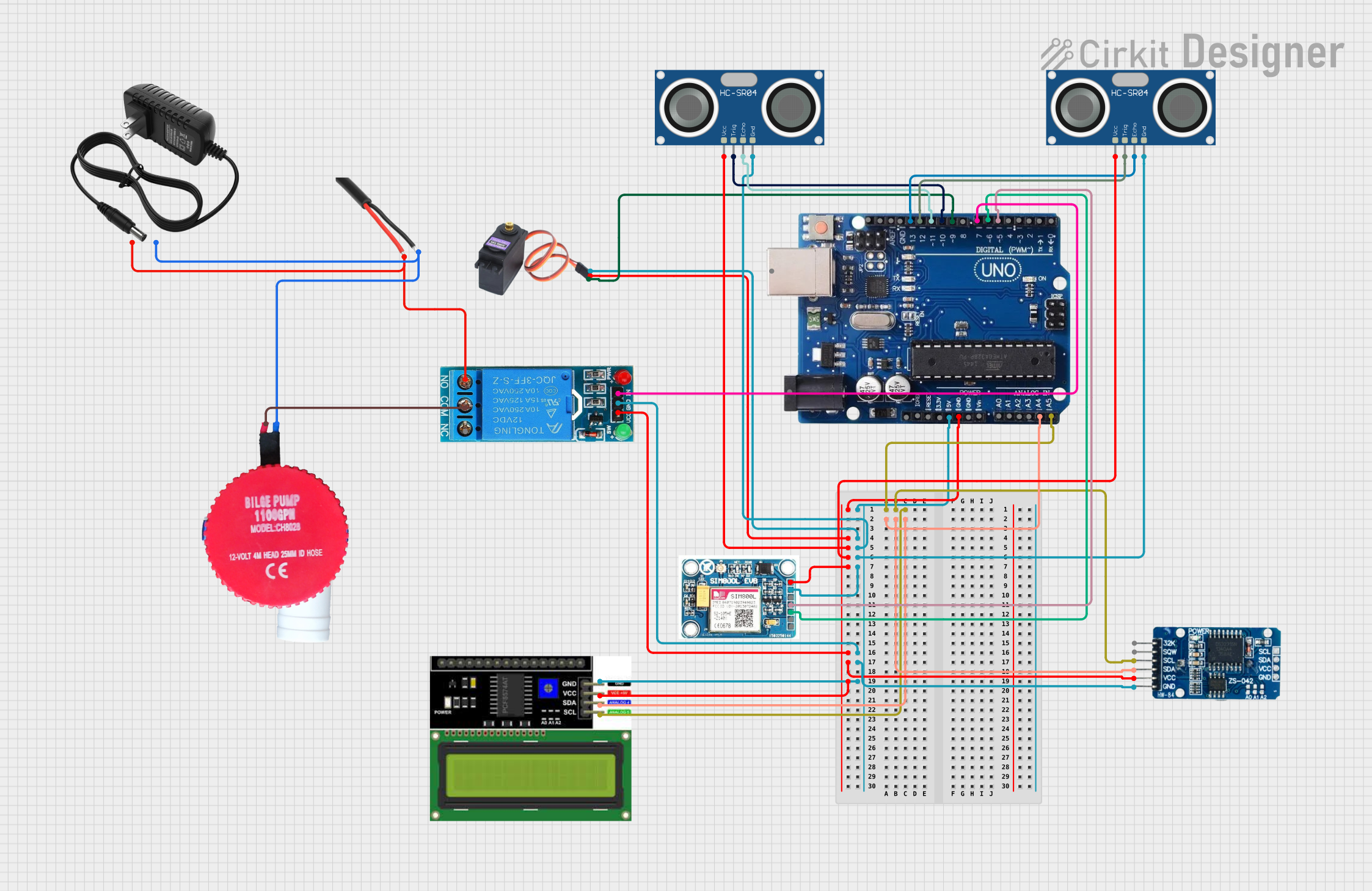
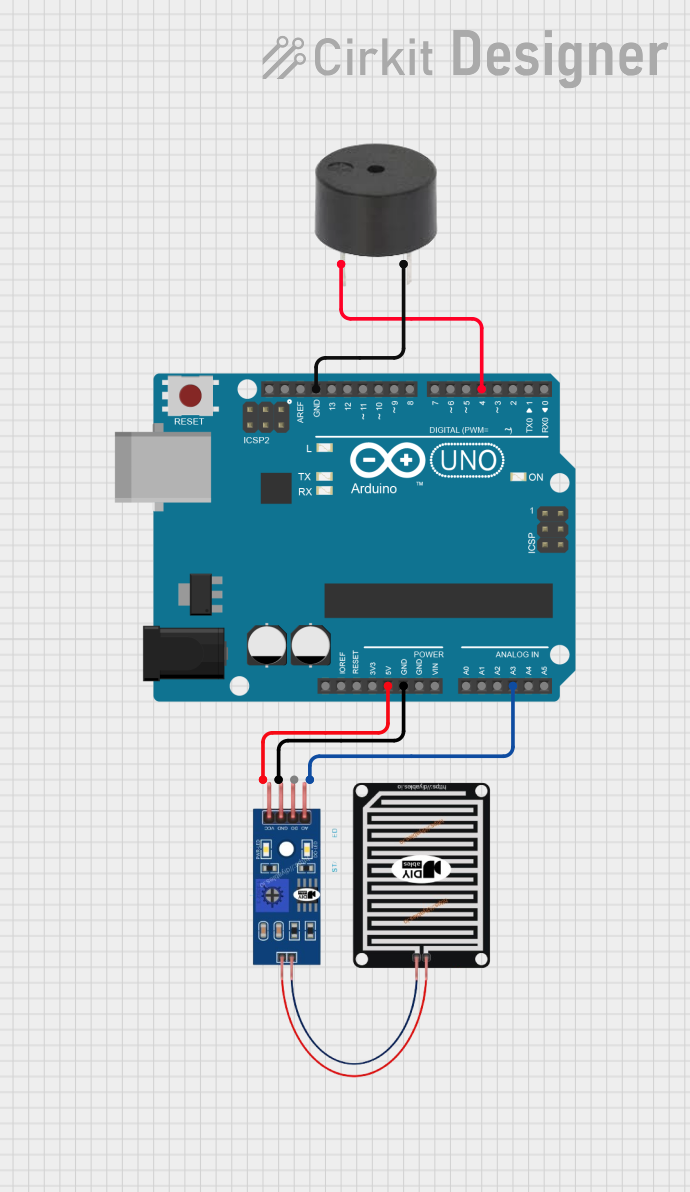
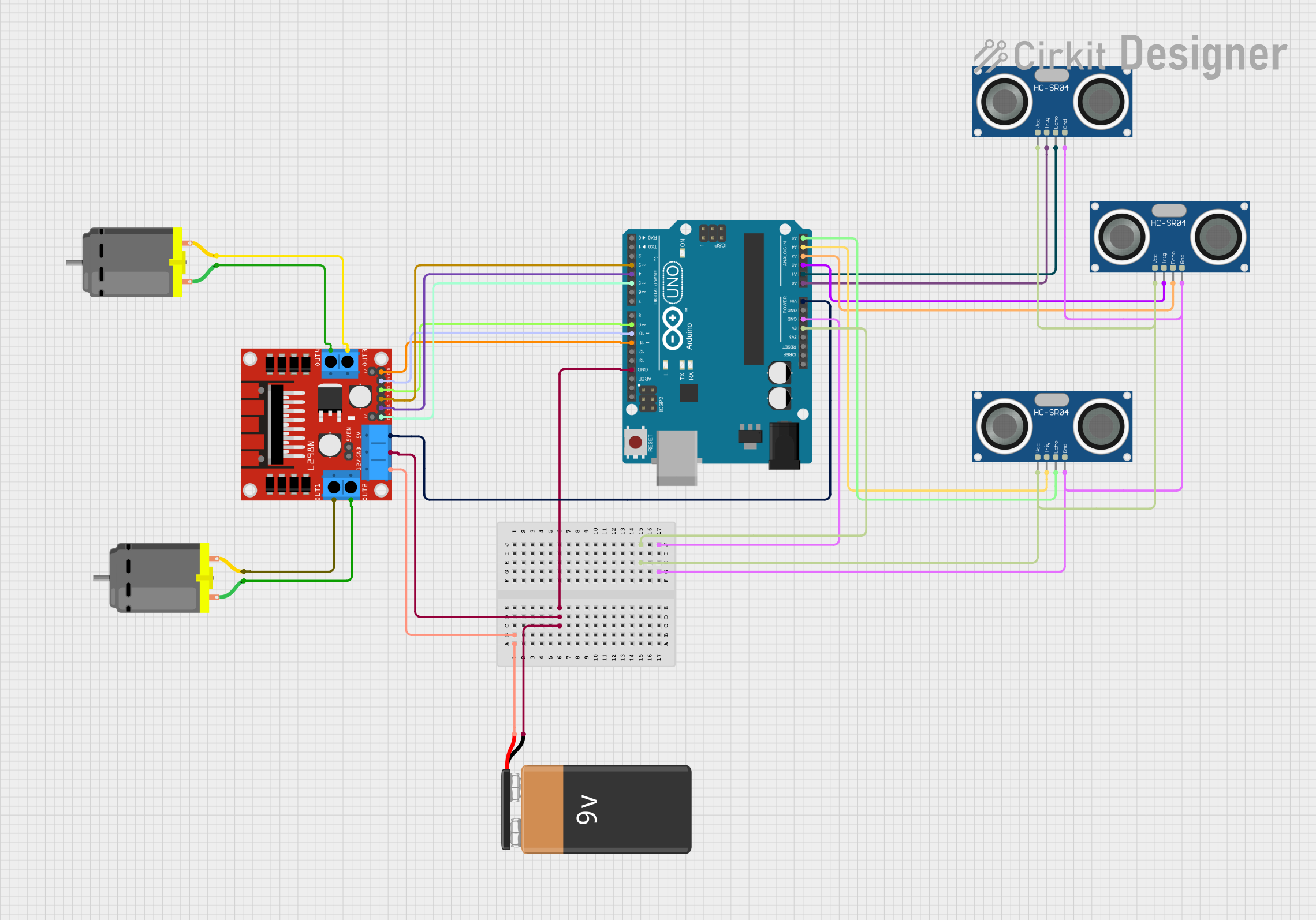
Explore Projects Built with ardino uno r3
Common Applications and Use Cases
- Prototyping electronic circuits
- Building IoT (Internet of Things) devices
- Robotics and automation projects
- Data acquisition and sensor interfacing
- Educational tools for learning programming and electronics
Technical Specifications
Key Technical Details
- Microcontroller: ATmega328P
- Operating Voltage: 5V
- Input Voltage (recommended): 7-12V
- Input Voltage (limit): 6-20V
- Digital I/O Pins: 14 (6 PWM outputs)
- Analog Input Pins: 6
- DC Current per I/O Pin: 20 mA
- Flash Memory: 32 KB (0.5 KB used by bootloader)
- SRAM: 2 KB
- EEPROM: 1 KB
- Clock Speed: 16 MHz
- USB Connector: Type-B
- Dimensions: 68.6 mm x 53.4 mm
- Weight: 25 g
Pin Configuration and Descriptions
The Arduino Uno R3 has a total of 28 pins, including digital, analog, power, and special-purpose pins. Below is a detailed breakdown:
Digital Pins
| Pin Number | Functionality | Description |
|---|---|---|
| 0 (RX) | Digital I/O, Serial Receive (RX) | Used for serial communication (UART). |
| 1 (TX) | Digital I/O, Serial Transmit (TX) | Used for serial communication (UART). |
| 2-13 | Digital I/O | General-purpose digital input/output. |
| 3, 5, 6, 9, 10, 11 | PWM Output | Pulse Width Modulation capable pins. |
Analog Pins
| Pin Number | Functionality | Description |
|---|---|---|
| A0-A5 | Analog Input | Reads analog signals (0-5V). |
Power Pins
| Pin Name | Functionality | Description |
|---|---|---|
| VIN | Input Voltage | External power input (7-12V recommended). |
| 5V | Regulated 5V Output | Powers external components. |
| 3.3V | Regulated 3.3V Output | Powers low-voltage components. |
| GND | Ground | Common ground for the circuit. |
| RESET | Reset | Resets the microcontroller. |
Special Pins
| Pin Name | Functionality | Description |
|---|---|---|
| IOREF | Reference Voltage | Provides voltage reference for shields. |
| AREF | Analog Reference | Sets reference voltage for analog inputs. |
Usage Instructions
How to Use the Arduino Uno R3 in a Circuit
Powering the Board:
- Connect the board to your computer using a USB Type-B cable for programming and power.
- Alternatively, use an external power supply (7-12V) via the VIN pin or the DC power jack.
Programming the Board:
- Install the Arduino IDE from the official website.
- Connect the board to your computer via USB.
- Select "Arduino Uno" as the board type in the IDE.
- Write your code in the IDE and upload it to the board.
Connecting Components:
- Use the digital pins for digital input/output operations (e.g., turning LEDs on/off).
- Use the analog pins to read sensor data (e.g., temperature, light intensity).
- Connect external modules (e.g., motors, displays) to the appropriate pins.
Important Considerations and Best Practices
- Avoid exceeding the maximum current rating (20 mA per pin) to prevent damage.
- Use pull-up or pull-down resistors for stable digital input signals.
- Ensure proper grounding for all connected components.
- Use a decoupling capacitor (e.g., 0.1 µF) near the power pins for noise reduction.
- Disconnect the board from power before making hardware changes.
Example Code: Blinking an LED
The following code demonstrates how to blink an LED connected to digital pin 13.
// This example code blinks an LED connected to pin 13 on the Arduino Uno R3.
// The LED will turn on for 1 second, then off for 1 second, repeatedly.

void setup() {
  pinMode(13, OUTPUT); // Set pin 13 as an output pin
}

void loop() {
  digitalWrite(13, HIGH); // Turn the LED on
  delay(1000);            // Wait for 1 second
  digitalWrite(13, LOW);  // Turn the LED off
  delay(1000);            // Wait for 1 second
}
Troubleshooting and FAQs
Common Issues and Solutions
Problem: The board is not detected by the computer.
- Solution: Ensure the USB cable is properly connected and functional. Try a different USB port or cable.
Problem: The code does not upload to the board.
- Solution: Verify that the correct board and COM port are selected in the Arduino IDE. Check for any conflicting drivers.
Problem: Components connected to the board are not working.
- Solution: Double-check the wiring and ensure components are connected to the correct pins. Verify that the power supply is adequate.
Problem: The board overheats during operation.
- Solution: Ensure the current draw of connected components does not exceed the board's limits. Use external power for high-current devices.
FAQs
Q: Can I power the Arduino Uno R3 with a battery?
- A: Yes, you can use a 9V battery connected to the DC power jack or VIN pin.
Q: What is the maximum voltage the analog pins can read?
- A: The analog pins can read voltages between 0 and 5V by default. Use the AREF pin for custom reference voltages.
Q: Can I use the Arduino Uno R3 for wireless communication?
- A: Yes, you can connect wireless modules like Bluetooth or Wi-Fi shields to the board.
Q: Is the Arduino Uno R3 compatible with all Arduino shields?
- A: Most Arduino shields are compatible, but always check the shield's specifications for compatibility.
This concludes the documentation for the Arduino Uno R3.