Cirkit Designer Logo
Cirkit Designer
Your all-in-one circuit design IDE
Home / 
Component Documentation

How to Use E22-900M30S: Examples, Pinouts, and Specs

Image of E22-900M30S
Cirkit Designer LogoDesign with E22-900M30S in Cirkit Designer

Introduction

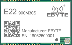
The E22-900M30S is a high-performance RF module manufactured by EBYTE. It is designed for wireless communication applications and operates in the 900 MHz frequency band. This module is ideal for low-power, long-range data transmission, making it a popular choice for IoT devices, remote sensor networks, and industrial automation systems.

Explore Projects Built with E22-900M30S

Use Cirkit Designer to design, explore, and prototype these projects online. Some projects support real-time simulation. Click "Open Project" to start designing instantly!
ESP32 and W5500 Ethernet Module-Based Smart Weather Station with Battery-Powered Motor
Image of ESP32 38Pin USBMicro: A project utilizing E22-900M30S in a practical application
This circuit integrates an ESP32 microcontroller with various sensors and an Ethernet module for data acquisition and network communication. It includes a DHT22 and SHTC3 sensor for environmental monitoring, a ZMPT101B for voltage measurement, and a 12V geared motor controlled by a 12V battery. The ESP32 handles sensor data and communicates via the W5500 Ethernet module.
Cirkit Designer LogoOpen Project in Cirkit Designer
ESP32-Based Multi-Sensor Monitoring System with GSM Notification and Power Management
Image of SSVM FINAL CIRCUIT: A project utilizing E22-900M30S in a practical application
This circuit features an ESP32 microcontroller as the central processing unit, interfaced with various sensors and modules for environmental monitoring and control. It includes a GSM SIM900 module for cellular communication, a water level sensor, an MQ135 air quality sensor, a heat flame sensor, and an ultrasonic ranging module for distance measurement. The circuit also incorporates a buzzer and LED for alerts, a pushbutton for user input, a vibration motor for haptic feedback, and a power management system consisting of a 12V battery, a rocker switch, and a buck converter to supply the required voltages.
Cirkit Designer LogoOpen Project in Cirkit Designer
Satellite-Based Timing and Navigation System with SDR and Atomic Clock Synchronization
Image of GPS 시스템 측정 구성도_Confirm: A project utilizing E22-900M30S in a practical application
This circuit appears to be a complex system involving power supply management, GPS and timing synchronization, and data communication. It includes a SI-TEX G1 Satellite Compass for GPS data, an XHTF1021 Atomic Rubidium Clock for precise timing, and Ettus USRP B200 units for software-defined radio communication. Power is supplied through various SMPS units and distributed via terminal blocks and DC jacks. Data communication is facilitated by Beelink MINI S12 N95 computers, RS232 splitters, and a 1000BASE-T Media Converter for network connectivity. RF Directional Couplers are used to interface antennas with the USRP units, and the entire system is likely contained within cases for protection and organization.
Cirkit Designer LogoOpen Project in Cirkit Designer
ESP32-Based Smart Environmental Monitoring System with Relay Control
Image of SOCOTECO: A project utilizing E22-900M30S in a practical application
This is a smart environmental monitoring and control system featuring an ESP32 microcontroller interfaced with a PZEM004T for power monitoring, relay modules for actuating bulbs and a fan, and an LCD for user interface. It includes flame, gas, and vibration sensors for safety monitoring purposes.
Cirkit Designer LogoOpen Project in Cirkit Designer

Explore Projects Built with E22-900M30S

Use Cirkit Designer to design, explore, and prototype these projects online. Some projects support real-time simulation. Click "Open Project" to start designing instantly!
Image of ESP32 38Pin USBMicro: A project utilizing E22-900M30S in a practical application
ESP32 and W5500 Ethernet Module-Based Smart Weather Station with Battery-Powered Motor
This circuit integrates an ESP32 microcontroller with various sensors and an Ethernet module for data acquisition and network communication. It includes a DHT22 and SHTC3 sensor for environmental monitoring, a ZMPT101B for voltage measurement, and a 12V geared motor controlled by a 12V battery. The ESP32 handles sensor data and communicates via the W5500 Ethernet module.
Cirkit Designer LogoOpen Project in Cirkit Designer
Image of SSVM FINAL CIRCUIT: A project utilizing E22-900M30S in a practical application
ESP32-Based Multi-Sensor Monitoring System with GSM Notification and Power Management
This circuit features an ESP32 microcontroller as the central processing unit, interfaced with various sensors and modules for environmental monitoring and control. It includes a GSM SIM900 module for cellular communication, a water level sensor, an MQ135 air quality sensor, a heat flame sensor, and an ultrasonic ranging module for distance measurement. The circuit also incorporates a buzzer and LED for alerts, a pushbutton for user input, a vibration motor for haptic feedback, and a power management system consisting of a 12V battery, a rocker switch, and a buck converter to supply the required voltages.
Cirkit Designer LogoOpen Project in Cirkit Designer
Image of GPS 시스템 측정 구성도_Confirm: A project utilizing E22-900M30S in a practical application
Satellite-Based Timing and Navigation System with SDR and Atomic Clock Synchronization
This circuit appears to be a complex system involving power supply management, GPS and timing synchronization, and data communication. It includes a SI-TEX G1 Satellite Compass for GPS data, an XHTF1021 Atomic Rubidium Clock for precise timing, and Ettus USRP B200 units for software-defined radio communication. Power is supplied through various SMPS units and distributed via terminal blocks and DC jacks. Data communication is facilitated by Beelink MINI S12 N95 computers, RS232 splitters, and a 1000BASE-T Media Converter for network connectivity. RF Directional Couplers are used to interface antennas with the USRP units, and the entire system is likely contained within cases for protection and organization.
Cirkit Designer LogoOpen Project in Cirkit Designer
Image of SOCOTECO: A project utilizing E22-900M30S in a practical application
ESP32-Based Smart Environmental Monitoring System with Relay Control
This is a smart environmental monitoring and control system featuring an ESP32 microcontroller interfaced with a PZEM004T for power monitoring, relay modules for actuating bulbs and a fan, and an LCD for user interface. It includes flame, gas, and vibration sensors for safety monitoring purposes.
Cirkit Designer LogoOpen Project in Cirkit Designer

Common Applications

  • Internet of Things (IoT) devices
  • Remote monitoring and control systems
  • Wireless sensor networks
  • Smart agriculture and environmental monitoring
  • Industrial automation and telemetry

Technical Specifications

Key Technical Details

Parameter Value
Operating Frequency 900 MHz
Modulation Type LoRa (Long Range)
Transmission Power Up to 30 dBm (1 Watt)
Communication Distance Up to 10 km (line of sight)
Supply Voltage 2.8V to 5.5V
Operating Current 120 mA (transmit mode)
Sleep Current < 5 µA
Data Rate 0.3 kbps to 19.2 kbps
Operating Temperature -40°C to +85°C
Dimensions 24 mm x 43 mm x 3 mm

Pin Configuration and Descriptions

The E22-900M30S module has 16 pins. Below is the pinout and description:

Pin Number Pin Name Description
1 M0 Mode selection pin 0 (used to configure operating modes)
2 M1 Mode selection pin 1 (used to configure operating modes)
3 RXD UART data input (connect to TXD of the microcontroller)
4 TXD UART data output (connect to RXD of the microcontroller)
5 AUX Auxiliary pin (indicates module status, e.g., busy or idle)
6 VCC Power supply input (2.8V to 5.5V)
7 GND Ground
8 SET Configuration pin (used for parameter settings)
9-16 NC Not connected (reserved for future use)

Usage Instructions

How to Use the E22-900M30S in a Circuit

  1. Power Supply: Connect the VCC pin to a stable power source (2.8V to 5.5V) and the GND pin to ground.
  2. UART Communication: Connect the RXD and TXD pins to the corresponding TXD and RXD pins of your microcontroller.
  3. Mode Selection: Use the M0 and M1 pins to configure the module's operating mode:
    • Mode 0 (Normal): M0 = 0, M1 = 0
    • Mode 1 (Wake-up): M0 = 1, M1 = 0
    • Mode 2 (Power-saving): M0 = 0, M1 = 1
    • Mode 3 (Sleep): M0 = 1, M1 = 1
  4. AUX Pin: Monitor the AUX pin to check the module's status. For example, a high signal indicates the module is idle, while a low signal indicates it is busy.
  5. Configuration: Use the SET pin to configure parameters such as frequency, data rate, and transmission power. This can be done via AT commands or a dedicated configuration tool.

Example: Connecting to an Arduino UNO

Below is an example of how to connect the E22-900M30S to an Arduino UNO and send data.

Wiring Diagram

E22-900M30S Pin Arduino UNO Pin
VCC 5V
GND GND
RXD D3 (via voltage divider if using 5V logic)
TXD D2
M0 D4
M1 D5
AUX D6

Arduino Code Example

#include <SoftwareSerial.h>

// Define pins for SoftwareSerial
#define E22_TX 2  // Connect to TXD of E22-900M30S
#define E22_RX 3  // Connect to RXD of E22-900M30S
#define M0_PIN 4  // Connect to M0 of E22-900M30S
#define M1_PIN 5  // Connect to M1 of E22-900M30S
#define AUX_PIN 6 // Connect to AUX of E22-900M30S

SoftwareSerial E22Serial(E22_RX, E22_TX);

void setup() {
  // Initialize serial communication
  Serial.begin(9600);       // For debugging
  E22Serial.begin(9600);    // Communication with E22-900M30S

  // Configure mode pins
  pinMode(M0_PIN, OUTPUT);
  pinMode(M1_PIN, OUTPUT);
  pinMode(AUX_PIN, INPUT);

  // Set module to Normal mode (M0 = 0, M1 = 0)
  digitalWrite(M0_PIN, LOW);
  digitalWrite(M1_PIN, LOW);

  Serial.println("E22-900M30S Initialized");
}

void loop() {
  // Send data to the E22 module
  E22Serial.println("Hello, E22-900M30S!");

  // Wait for the module to process the data
  delay(1000);

  // Check for incoming data
  if (E22Serial.available()) {
    String receivedData = E22Serial.readString();
    Serial.print("Received: ");
    Serial.println(receivedData);
  }

  delay(2000); // Delay between transmissions
}

Important Considerations

  • Voltage Levels: The E22-900M30S operates at 3.3V logic levels. If using a 5V microcontroller (e.g., Arduino UNO), use a voltage divider or level shifter for the RXD pin.
  • Antenna: Ensure a proper 900 MHz antenna is connected to the module for optimal performance.
  • Distance: The maximum communication range (10 km) is achievable only in line-of-sight conditions with minimal interference.

Troubleshooting and FAQs

Common Issues and Solutions

  1. No Communication Between Devices

    • Ensure the RXD and TXD pins are correctly connected.
    • Verify that both modules are configured with the same frequency, data rate, and other parameters.
  2. Short Communication Range

    • Check the antenna connection and ensure it is suitable for the 900 MHz band.
    • Avoid obstacles and interference sources between the transmitter and receiver.
  3. Module Not Responding

    • Verify the power supply voltage (2.8V to 5.5V).
    • Check the AUX pin to ensure the module is not busy.
  4. Data Corruption

    • Ensure the baud rate of the microcontroller matches the module's UART baud rate.
    • Use shielded cables to reduce electromagnetic interference.

FAQs

Q: Can I use the E22-900M30S with a 5V microcontroller?
A: Yes, but you must use a voltage divider or level shifter for the RXD pin to avoid damaging the module.

Q: How do I configure the module's parameters?
A: Parameters can be configured using AT commands via UART or a dedicated configuration tool provided by EBYTE.

Q: What is the maximum data rate of the module?
A: The maximum data rate is 19.2 kbps, which is suitable for low-power, long-range applications.