How to Use Adafruit OLED Monochrome 1.3in 128x64 with STEMMA QT: Examples, Pinouts, and Specs
Introduction
The Adafruit OLED Monochrome 1.3in 128x64 with STEMMA QT is a compact and versatile display module that offers high contrast and excellent readability under various lighting conditions. Its 128x64 pixel resolution provides sufficient detail for text and simple graphics, making it suitable for a wide range of applications, including wearable devices, portable instruments, and embedded systems. The inclusion of the STEMMA QT connector simplifies interfacing with other compatible devices, enabling quick prototyping and development.
Explore Projects Built with Adafruit OLED Monochrome 1.3in 128x64 with STEMMA QT

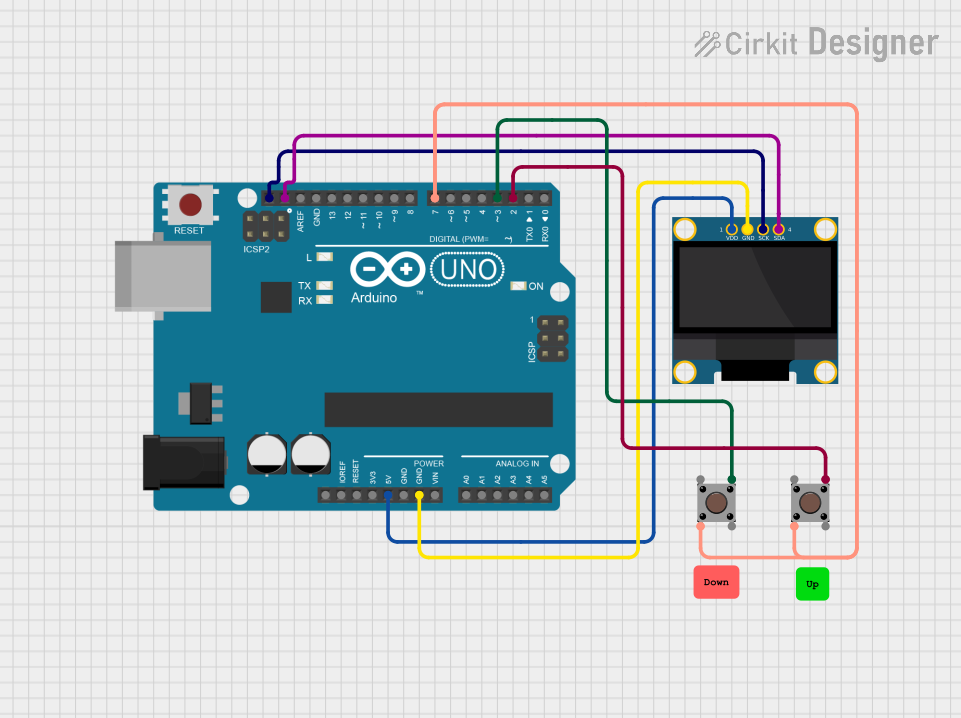

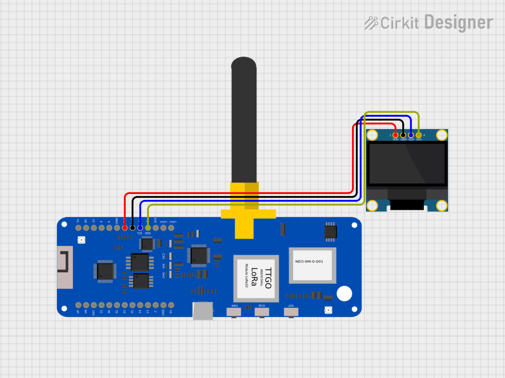
Explore Projects Built with Adafruit OLED Monochrome 1.3in 128x64 with STEMMA QT
Common Applications and Use Cases
- Wearable electronics
- User interfaces for small-scale projects
- Data monitoring displays
- Portable instrumentation
- Battery-powered devices
Technical Specifications
Key Technical Details
- Display Type: Monochrome OLED
- Resolution: 128x64 pixels
- Screen Size: 1.3 inches diagonal
- Interface: I2C
- Operating Voltage: 3.3V to 5V
- Driver IC: SSD1306
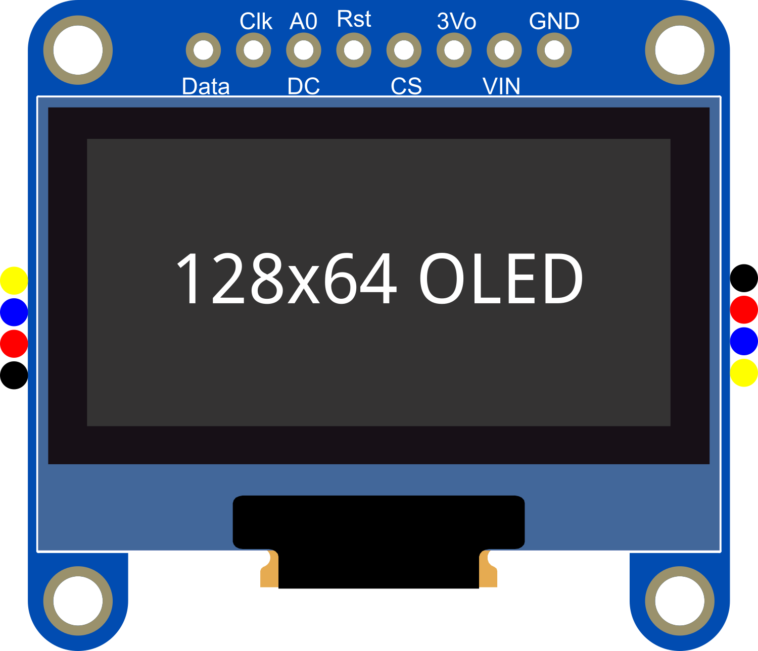
Pin Configuration and Descriptions
| Pin Number | Pin Name | Description |
|---|---|---|
| 1 | GND | Ground |
| 2 | VCC | Power supply (3.3V - 5V) |
| 3 | SCL | I2C clock line |
| 4 | SDA | I2C data line |
| 5 | RST | Reset pin (optional, can be left NC) |
Usage Instructions
How to Use the Component in a Circuit
- Power Connections: Connect the VCC pin to a 3.3V or 5V power supply, and the GND pin to the ground of your system.
- Data Connections: Connect the SCL and SDA pins to the I2C clock and data lines on your microcontroller.
- Reset (Optional): The RST pin can be connected to a digital pin on your microcontroller if you wish to control the reset function programmatically.
Important Considerations and Best Practices
- Ensure that the power supply voltage does not exceed the specified maximum to prevent damage to the display.
- Use pull-up resistors on the I2C lines if they are not already present on your microcontroller board.
- When using with a 5V system, ensure that the I2C lines are level-shifted to be compatible with the display's logic level.
Example Code for Arduino UNO
#include <Wire.h>
#include <Adafruit_GFX.h>
#include <Adafruit_SSD1306.h>

#define SCREEN_WIDTH 128 // OLED display width, in pixels
#define SCREEN_HEIGHT 64 // OLED display height, in pixels

// Declaration for an SSD1306 display connected to I2C (SCL, SDA pins)
Adafruit_SSD1306 display(SCREEN_WIDTH, SCREEN_HEIGHT, &Wire);

void setup() {
  // Initialize with the I2C addr 0x3C (for the 128x64)
  if(!display.begin(SSD1306_SWITCHCAPVCC, 0x3C)) {
    Serial.println(F("SSD1306 allocation failed"));
    for(;;); // Don't proceed, loop forever
  }

  // Clear the buffer
  display.clearDisplay();

  // Draw a single pixel in white
  display.drawPixel(10, 10, SSD1306_WHITE);

  // Display the drawing
  display.display();
}

void loop() {
  // Nothing to do here
}
Troubleshooting and FAQs
Common Issues Users Might Face
- Display Not Powering On: Check the power connections and ensure the voltage is within the specified range.
- No Data on Display: Verify that the I2C connections are correct and that the correct I2C address is used in the code.
- Garbled or Incomplete Data: Ensure that the display is properly initialized in your setup code and that the display buffer is being correctly managed.
Solutions and Tips for Troubleshooting
- Double-check wiring, especially the I2C lines and power connections.
- Use a multimeter to verify that the correct voltage is reaching the display.
- Check for soldering issues on the STEMMA QT connector if you're using a custom setup.
- Consult the Adafruit SSD1306 library documentation for additional functions and features.
FAQs
Q: Can I use this display with a 5V microcontroller? A: Yes, but ensure that the I2C lines are level-shifted to be compatible with the display's logic level.
Q: How do I install the Adafruit SSD1306 library? A: You can install the library through the Arduino Library Manager by searching for "Adafruit SSD1306" and installing it.
Q: What is the STEMMA QT connector for? A: The STEMMA QT connector allows for easy plug-and-play connection with other STEMMA QT or Qwiic compatible devices without soldering.
Q: Can I display images on this OLED? A: Yes, you can display bitmap images, but they need to be converted to a monochrome format suitable for the display's resolution.
Q: How do I control the brightness of the display? A: The Adafruit SSD1306 library provides functions to adjust the contrast of the display, which can be used to control brightness.