How to Use Pololu 12V 4.5A DC-DC Step-Down Voltage Regulator: Examples, Pinouts, and Specs
Introduction
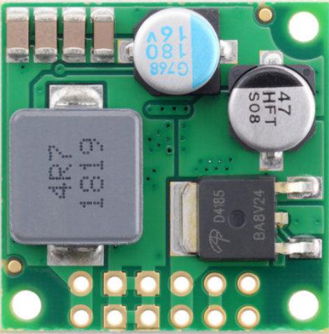
The Pololu 12V 4.5A DC-DC Step-Down Voltage Regulator is a compact and efficient device designed to convert a higher DC input voltage into a stable, lower DC output voltage. With a maximum output current of 4.5A, this regulator is ideal for powering a wide range of electronic devices, including microcontrollers, sensors, motors, and other low-voltage components. Its high efficiency and small form factor make it suitable for applications where space and power efficiency are critical.
Explore Projects Built with Pololu 12V 4.5A DC-DC Step-Down Voltage Regulator


Explore Projects Built with Pololu 12V 4.5A DC-DC Step-Down Voltage Regulator
Common Applications and Use Cases
- Powering microcontrollers (e.g., Arduino, Raspberry Pi) from higher voltage sources.
- Supplying stable voltage to sensors, actuators, and communication modules.
- Battery-powered systems requiring efficient voltage conversion.
- Robotics and automation projects.
- Industrial and automotive electronics.
Technical Specifications
The following table outlines the key technical details of the Pololu 12V 4.5A DC-DC Step-Down Voltage Regulator:
| Parameter | Value |
|---|---|
| Manufacturer | Pololu |
| Part Number | 12V 4.5A DC-DC Step-Down Voltage Regulator |
| Input Voltage Range | 13.5V to 38V |
| Output Voltage | 12V (fixed) |
| Maximum Output Current | 4.5A |
| Efficiency | Up to 95% (depending on input voltage and load) |
| Switching Frequency | ~400 kHz |
| Operating Temperature | -40°C to +85°C |
| Dimensions | 25.4 mm × 25.4 mm × 12.7 mm |
| Weight | 6.5 g |
| Protection Features | Over-current, over-temperature, and short-circuit protection |
Pin Configuration and Descriptions
The Pololu 12V 4.5A DC-DC Step-Down Voltage Regulator has three main pins for input and output connections:
| Pin Name | Description |
|---|---|
| VIN | Input voltage pin. Connect to the positive terminal of the input power source. |
| GND | Ground pin. Connect to the negative terminal of the input power source. |
| VOUT | Output voltage pin. Provides a regulated 12V DC output. |
Usage Instructions
How to Use the Component in a Circuit
Connect the Input Voltage:
- Connect the VIN pin to the positive terminal of your DC power source (13.5V to 38V).
- Connect the GND pin to the negative terminal of your DC power source.
Connect the Output Voltage:
- Connect the VOUT pin to the positive terminal of the load (e.g., microcontroller, motor).
- Connect the GND pin to the ground of the load.
Verify Connections:
- Double-check all connections to ensure proper polarity and secure wiring.
Power On:
- Turn on the input power source. The regulator will provide a stable 12V output to the connected load.
Important Considerations and Best Practices
- Input Voltage Range: Ensure the input voltage is within the specified range (13.5V to 38V). Exceeding this range may damage the regulator.
- Heat Dissipation: At high loads, the regulator may generate heat. Use proper ventilation or a heatsink if necessary.
- Current Limitations: Do not exceed the maximum output current of 4.5A to avoid triggering over-current protection.
- Wiring: Use appropriately rated wires to handle the input and output currents safely.
- Polarity: Ensure correct polarity for all connections to prevent damage to the regulator and connected devices.
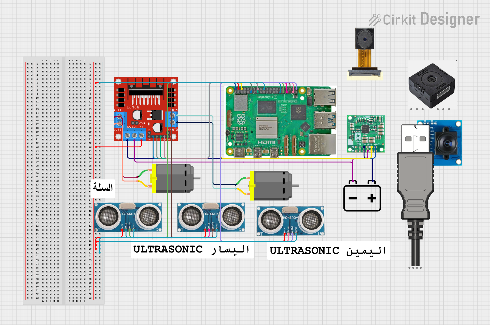
Example: Using with an Arduino UNO
The Pololu 12V 4.5A DC-DC Step-Down Voltage Regulator can be used to power an Arduino UNO from a 24V DC power source. Below is an example wiring diagram and Arduino code to blink an LED:
Wiring Diagram
- Connect the VIN pin of the regulator to the positive terminal of the 24V power source.
- Connect the GND pin of the regulator to the negative terminal of the 24V power source.
- Connect the VOUT pin of the regulator to the VIN pin of the Arduino UNO.
- Connect the GND pin of the regulator to the GND pin of the Arduino UNO.
Arduino Code
// This code blinks an LED connected to pin 13 of the Arduino UNO.
// Ensure the regulator provides a stable 12V to the Arduino's VIN pin.

void setup() {
  pinMode(13, OUTPUT); // Set pin 13 as an output pin
}

void loop() {
  digitalWrite(13, HIGH); // Turn the LED on
  delay(1000);            // Wait for 1 second
  digitalWrite(13, LOW);  // Turn the LED off
  delay(1000);            // Wait for 1 second
}
Troubleshooting and FAQs
Common Issues Users Might Face
No Output Voltage:
- Cause: Incorrect input voltage or loose connections.
- Solution: Verify that the input voltage is within the specified range (13.5V to 38V) and check all connections.
Overheating:
- Cause: High load current or insufficient ventilation.
- Solution: Reduce the load current or improve heat dissipation using a heatsink or fan.
Output Voltage Drops Under Load:
- Cause: Exceeding the maximum output current of 4.5A.
- Solution: Ensure the load current does not exceed 4.5A. Use a higher-capacity regulator if needed.
Regulator Shuts Down:
- Cause: Over-current or over-temperature protection triggered.
- Solution: Reduce the load or improve cooling to prevent thermal shutdown.
Solutions and Tips for Troubleshooting
- Use a multimeter to measure input and output voltages to verify proper operation.
- Check for short circuits or incorrect wiring that may cause the regulator to malfunction.
- If the regulator is not functioning as expected, disconnect all loads and test it with a minimal load to isolate the issue.
By following these guidelines and best practices, you can effectively use the Pololu 12V 4.5A DC-DC Step-Down Voltage Regulator in your projects.