
How to Use loadcell: Examples, Pinouts, and Specs
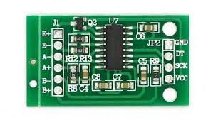
 Design with loadcell in Cirkit Designer
Introduction
A load cell, such as the AAA-003 manufactured by AAA, is a transducer that converts force or weight into an electrical signal. This component is widely used in scales, weighing systems, and industrial automation to measure weight or load with high precision. The AAA-003 load cell is designed for reliability and accuracy, making it suitable for applications ranging from laboratory balances to heavy-duty industrial weighing systems.
Explore Projects Built with loadcell
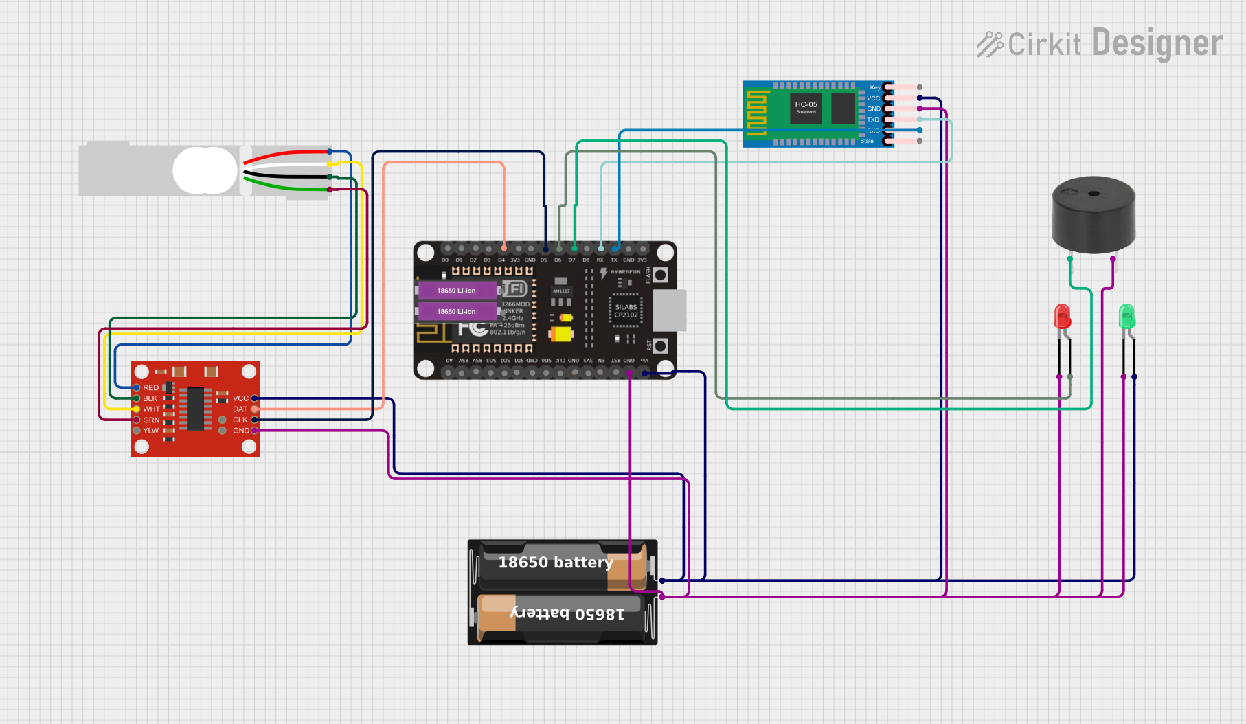 Open Project in Cirkit Designer
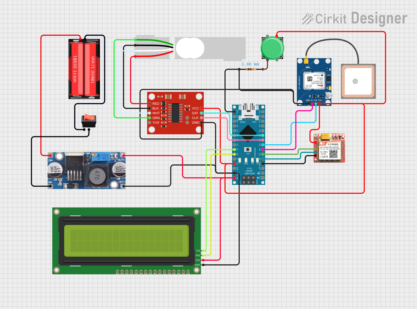 Open Project in Cirkit Designer
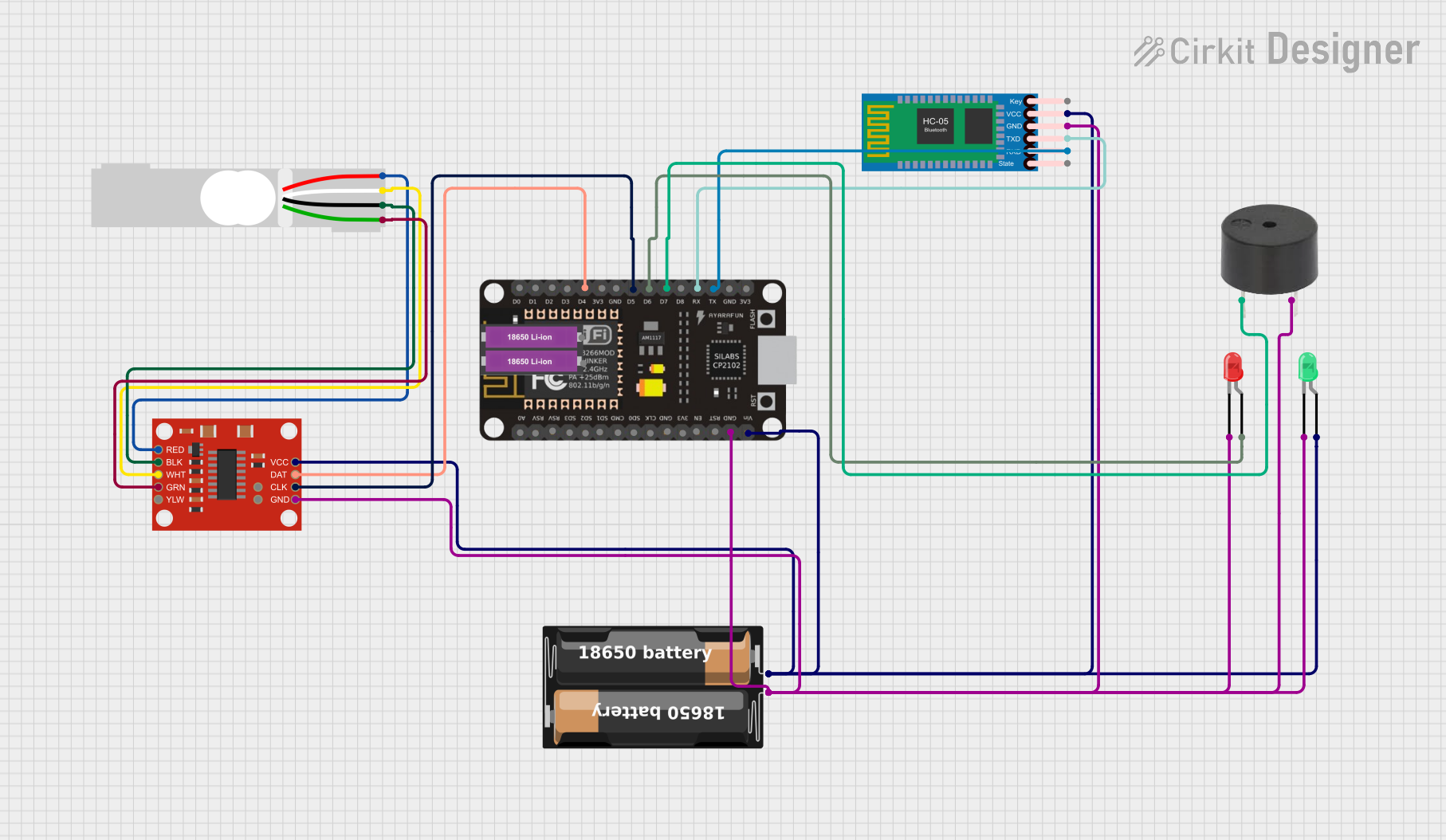 Open Project in Cirkit Designer
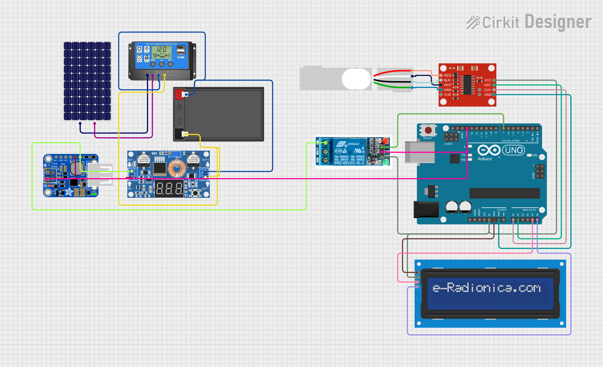 Open Project in Cirkit Designer
Explore Projects Built with loadcell
Open Project in Cirkit DesignerOpen Project in Cirkit DesignerOpen Project in Cirkit DesignerOpen Project in Cirkit DesignerCommon Applications
- Digital weighing scales
- Industrial automation and process control
- Force measurement in testing equipment
- Load monitoring in structural engineering
- Robotics and prosthetics
Technical Specifications
The AAA-003 load cell is a strain gauge-based sensor that operates by detecting minute deformations in its structure when a force is applied. Below are the key technical details:
General Specifications
| Parameter | Value |
|---|---|
| Manufacturer | AAA |
| Part ID | 003 |
| Type | Strain gauge load cell |
| Rated Load Capacity | 5 kg |
| Output Sensitivity | 2 mV/V |
| Excitation Voltage | 5V to 12V DC |
| Operating Temperature | -10°C to 50°C |
| Accuracy Class | ±0.02% |
| Material | Aluminum alloy |
| Dimensions | 80 mm x 12.7 mm x 12.7 mm |
Pin Configuration
The AAA-003 load cell typically has four wires for electrical connections. The pinout is as follows:
| Wire Color | Function | Description |
|---|---|---|
| Red | Excitation (+) | Positive voltage input for excitation |
| Black | Excitation (-) | Negative voltage input for excitation (ground) |
| Green | Signal (+) | Positive output signal |
| White | Signal (-) | Negative output signal |
Usage Instructions
How to Use the Load Cell in a Circuit
Wiring the Load Cell:
- Connect the red wire to the positive terminal of the excitation voltage source (e.g., 5V).
- Connect the black wire to the ground terminal of the excitation voltage source.
- Connect the green wire to the positive input of an amplifier or ADC (Analog-to-Digital Converter).
- Connect the white wire to the negative input of the amplifier or ADC.
Amplification and Signal Processing:
- The output signal of the load cell is in millivolts (mV) and requires amplification.
- Use a load cell amplifier module (e.g., HX711) to amplify the signal and convert it to a digital format.
Connecting to an Arduino UNO:
- Connect the load cell to an HX711 amplifier module.
- Wire the HX711 module to the Arduino UNO as follows:
VCCof HX711 to5Von Arduino.GNDof HX711 toGNDon Arduino.DTof HX711 to digital pinA2on Arduino.SCKof HX711 to digital pinA3on Arduino.
Arduino Code Example: Below is an example code to read data from the load cell using the HX711 module:
#include "HX711.h" // Include HX711 library // Define HX711 pins #define DT A2 // Data pin connected to Arduino pin A2 #define SCK A3 // Clock pin connected to Arduino pin A3 HX711 scale; // Create an instance of the HX711 class void setup() { Serial.begin(9600); // Initialize serial communication scale.begin(DT, SCK); // Initialize HX711 with defined pins scale.set_scale(); // Set the scale factor (calibration required) scale.tare(); // Reset the scale to zero Serial.println("Load cell initialized."); } void loop() { // Read weight from the load cell float weight = scale.get_units(); // Get weight in user-defined units Serial.print("Weight: "); Serial.print(weight); Serial.println(" kg"); // Display weight in kilograms delay(500); // Wait for 500 ms before the next reading }Note: Calibration is required to set the correct scale factor for accurate weight measurements. Refer to the HX711 library documentation for calibration instructions.
Important Considerations
- Ensure the load cell is mounted securely to avoid measurement errors caused by vibrations or misalignment.
- Avoid overloading the load cell beyond its rated capacity (5 kg for the AAA-003) to prevent permanent damage.
- Use shielded cables for wiring to minimize noise interference in the signal.
- Perform regular calibration to maintain accuracy over time.
Troubleshooting and FAQs
Common Issues and Solutions
No Output Signal:
- Cause: Incorrect wiring or loose connections.
- Solution: Verify all connections, especially the excitation and signal wires.
Inconsistent Readings:
- Cause: Mechanical vibrations or unstable mounting.
- Solution: Ensure the load cell is securely mounted and isolated from vibrations.
Output Signal Too Weak:
- Cause: Insufficient excitation voltage or damaged load cell.
- Solution: Check the excitation voltage and ensure it is within the specified range (5V to 12V). Replace the load cell if damaged.
Incorrect Weight Measurements:
- Cause: Calibration not performed or incorrect scale factor.
- Solution: Perform calibration using known weights and adjust the scale factor in the code.
FAQs
Can the AAA-003 load cell measure weights above 5 kg?
- No, the AAA-003 is rated for a maximum load of 5 kg. Exceeding this limit may damage the load cell.
What is the lifespan of the AAA-003 load cell?
- The lifespan depends on usage conditions, but with proper handling and within rated limits, it can last for several years.
Can I use the AAA-003 load cell with a Raspberry Pi?
- Yes, the AAA-003 can be used with a Raspberry Pi when paired with an HX711 amplifier module. Use GPIO pins on the Raspberry Pi for data and clock connections.
How do I protect the load cell from environmental factors?
- Use a protective enclosure or coating to shield the load cell from moisture, dust, and extreme temperatures.
By following this documentation, users can effectively integrate the AAA-003 load cell into their projects and achieve accurate weight measurements.