How to Use 3P Motor Reversing Module : Examples, Pinouts, and Specs
Introduction
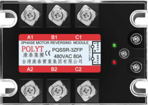
The 3P Motor Reversing Module by B is a compact and efficient device designed to control the direction of a DC motor by reversing the polarity of the voltage applied to the motor terminals. This functionality enables seamless forward and reverse operation of the motor, making it an essential component in motor control systems.
Explore Projects Built with 3P Motor Reversing Module
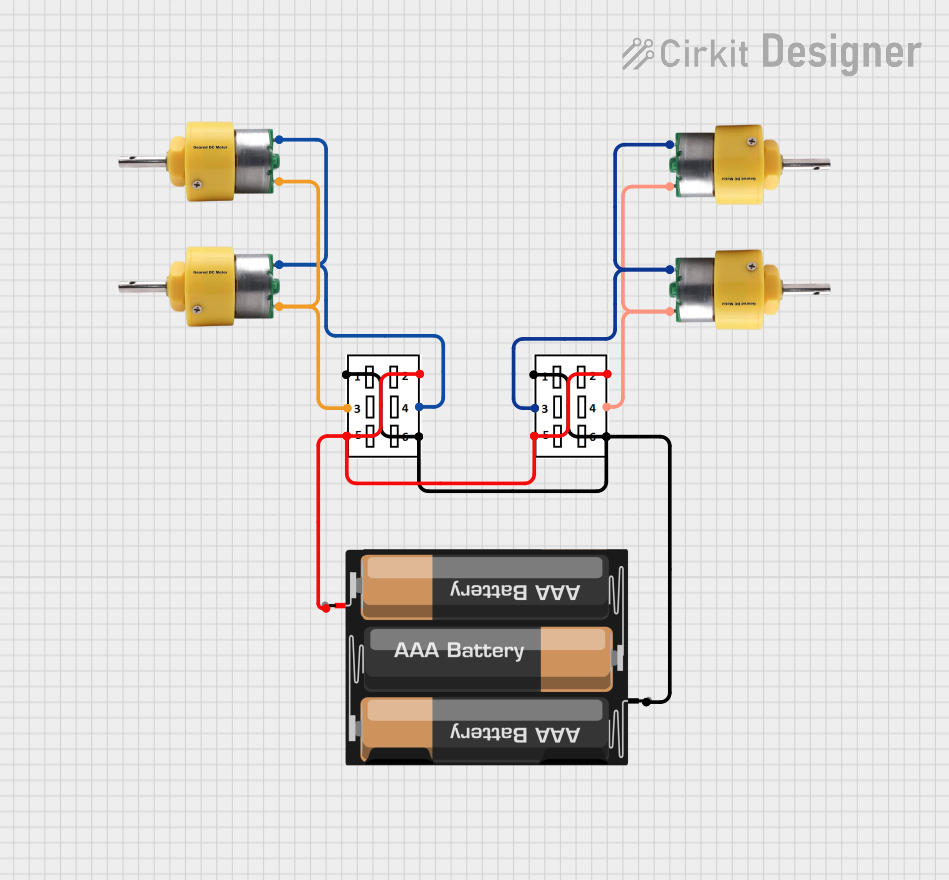
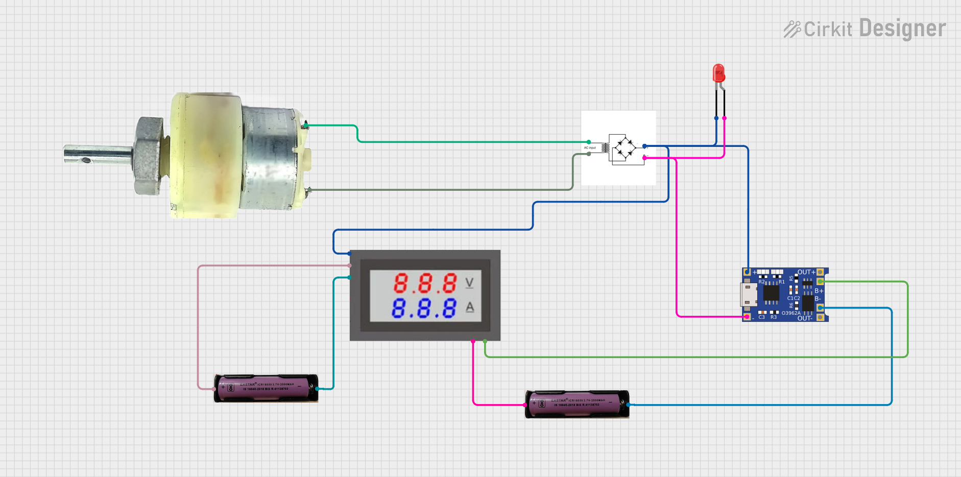
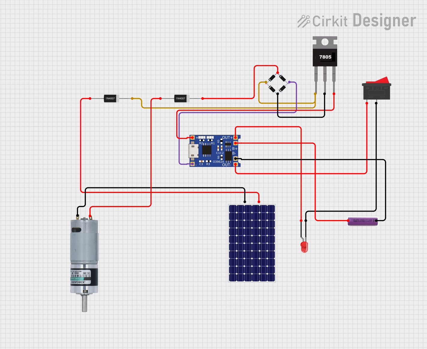
Explore Projects Built with 3P Motor Reversing Module
Common Applications and Use Cases
- Robotics: Controlling the movement direction of robot wheels or arms.
- Conveyor systems: Switching the direction of conveyor belts.
- Automated gates and doors: Reversing motor direction for opening and closing.
- DIY projects: Any application requiring bidirectional motor control.
Technical Specifications
The following table outlines the key technical details of the 3P Motor Reversing Module:
| Parameter | Value |
|---|---|
| Operating Voltage | 5V to 30V DC |
| Maximum Current | 10A |
| Control Signal Voltage | 3.3V to 5V (logic level) |
| Dimensions | 50mm x 30mm x 15mm |
| Operating Temperature | -20°C to 85°C |
| Weight | 20g |
Pin Configuration and Descriptions
The module features a 3-pin input interface and a 2-pin motor output interface. The pin configuration is as follows:
Input Pins
| Pin | Name | Description |
|---|---|---|
| 1 | VCC | Positive power supply input (5V to 30V DC). |
| 2 | GND | Ground connection. |
| 3 | IN | Control signal input. A HIGH signal (3.3V-5V) reverses the motor direction. |
Output Pins
| Pin | Name | Description |
|---|---|---|
| 1 | MOTOR+ | Positive terminal of the motor. |
| 2 | MOTOR- | Negative terminal of the motor. |
Usage Instructions
How to Use the Component in a Circuit
- Power Supply: Connect the VCC pin to a DC power source (5V to 30V) and the GND pin to the ground of the same power source.
- Motor Connection: Connect the motor terminals to the MOTOR+ and MOTOR- output pins.
- Control Signal: Use a microcontroller (e.g., Arduino UNO) or a manual switch to provide a control signal to the IN pin:
- A LOW signal (0V) will drive the motor in the forward direction.
- A HIGH signal (3.3V to 5V) will reverse the motor direction.
Important Considerations and Best Practices
- Ensure the power supply voltage matches the motor's operating voltage to avoid damage.
- Do not exceed the maximum current rating of 10A to prevent overheating or failure.
- Use appropriate heat dissipation methods (e.g., heatsinks) if operating near the maximum current limit.
- For microcontroller-based control, use a pull-down resistor on the IN pin to prevent floating signals.
Example: Connecting to an Arduino UNO
Below is an example of how to control the 3P Motor Reversing Module using an Arduino UNO:
Circuit Connections
- Connect the VCC pin of the module to the Arduino's 5V pin.
- Connect the GND pin of the module to the Arduino's GND pin.
- Connect the IN pin of the module to Arduino digital pin 7.
- Connect the motor terminals to the MOTOR+ and MOTOR- pins of the module.
Arduino Code
// Define the control pin for the motor reversing module
const int motorControlPin = 7;

void setup() {
  // Set the motor control pin as an output
  pinMode(motorControlPin, OUTPUT);
}

void loop() {
  // Drive the motor forward
  digitalWrite(motorControlPin, LOW);
  delay(5000); // Run forward for 5 seconds

  // Reverse the motor direction
  digitalWrite(motorControlPin, HIGH);
  delay(5000); // Run in reverse for 5 seconds
}
Troubleshooting and FAQs
Common Issues and Solutions
Motor Does Not Run:
- Verify that the power supply voltage is within the specified range (5V to 30V).
- Check all connections, especially the motor terminals and control signal input.
- Ensure the motor is functional by testing it directly with a power source.
Motor Runs in Only One Direction:
- Confirm that the control signal (IN pin) is toggling between HIGH and LOW.
- Check the Arduino code or control circuit for errors.
Module Overheats:
- Ensure the motor's current draw does not exceed 10A.
- Add a heatsink or improve ventilation around the module.
Motor Vibrates but Does Not Turn:
- Check for loose connections at the motor terminals.
- Verify that the motor is not overloaded or mechanically jammed.
FAQs
Q: Can I use this module with a 3.3V microcontroller?
A: Yes, the IN pin is compatible with 3.3V logic levels.
Q: Is this module suitable for AC motors?
A: No, the 3P Motor Reversing Module is designed for DC motors only.
Q: Can I control the motor speed with this module?
A: No, this module is designed for direction control only. Use a motor driver with PWM support for speed control.
Q: What happens if I reverse the VCC and GND connections?
A: Reversing the power supply connections may damage the module. Always double-check your wiring before powering on.
This concludes the documentation for the 3P Motor Reversing Module by B. For further assistance, refer to the manufacturer's support resources.