How to Use Audio Converter & Amplifier (Back): Examples, Pinouts, and Specs
Introduction
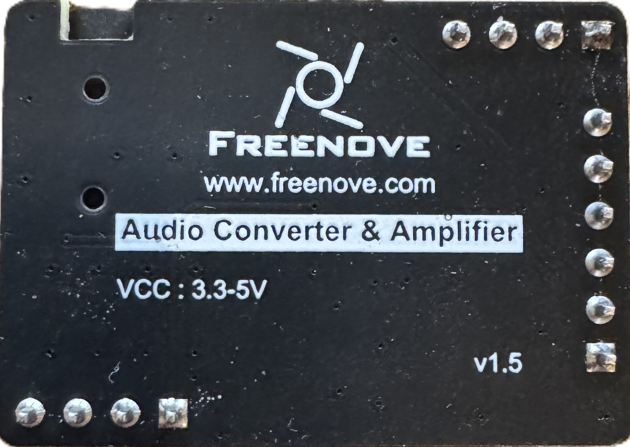
The Audio Converter & Amplifier (Back), manufactured by FREENOVE, with part ID ES7148/PAM8403, is a versatile device designed to convert audio signals from one format to another while amplifying the signal. This component is ideal for applications requiring enhanced sound quality and volume, such as driving speakers or headphones. It combines the functionality of an audio signal converter and a low-power audio amplifier, making it a compact and efficient solution for audio projects.
Explore Projects Built with Audio Converter & Amplifier (Back)
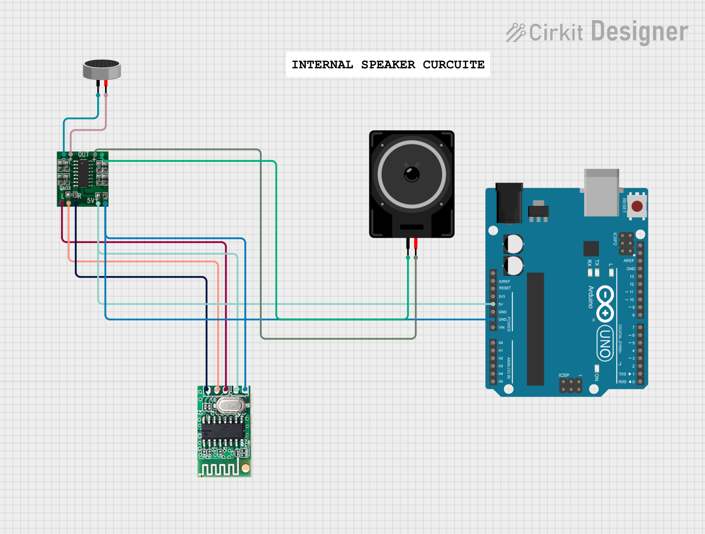
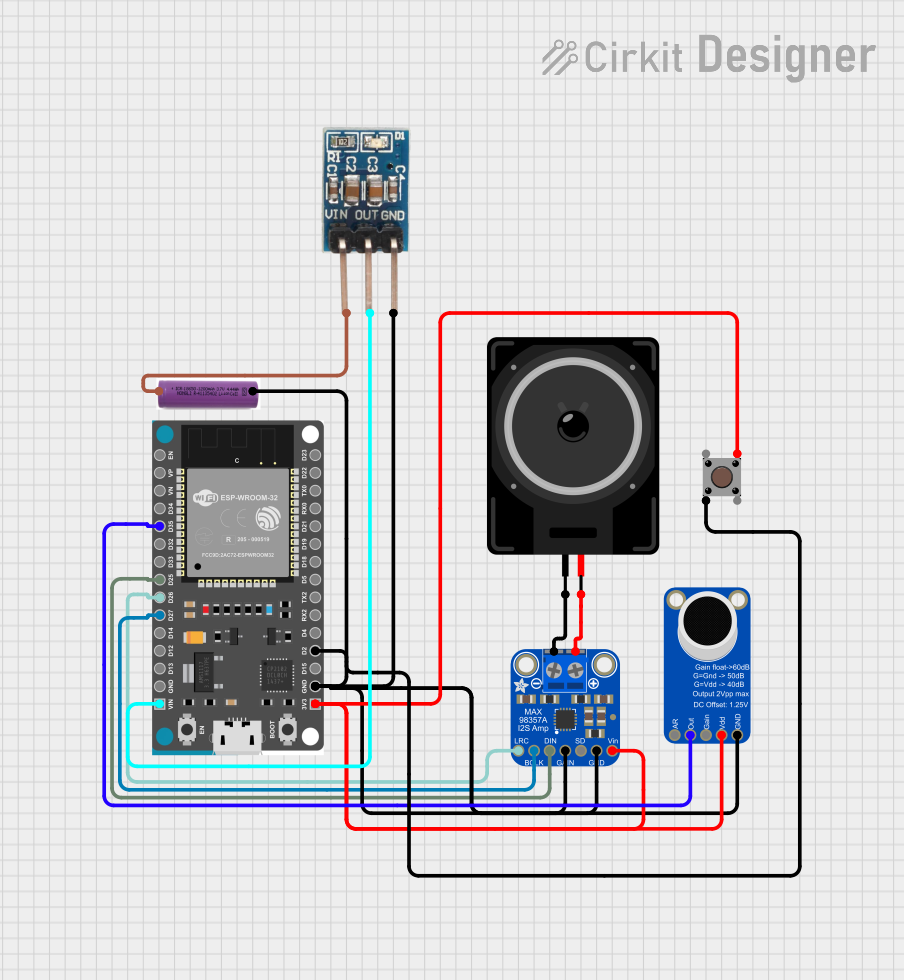
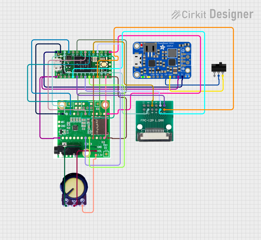
Explore Projects Built with Audio Converter & Amplifier (Back)
Common Applications and Use Cases
- Portable speaker systems
- DIY audio projects
- Audio signal processing and conversion
- Headphone amplifiers
- Integration with microcontrollers like Arduino for audio playback
Technical Specifications
Key Technical Details
| Parameter | Value |
|---|---|
| Manufacturer | FREENOVE |
| Part ID | ES7148/PAM8403 |
| Operating Voltage | 2.5V to 5.5V |
| Output Power | 3W per channel (stereo) at 4Ω, 5V supply |
| Signal-to-Noise Ratio | ≥ 90 dB |
| Total Harmonic Distortion | ≤ 0.1% |
| Input Signal Format | I2S (Inter-IC Sound) |
| Output Signal Format | Analog audio |
| Amplifier Type | Class D |
| Efficiency | Up to 90% |
| Operating Temperature | -40°C to +85°C |
Pin Configuration and Descriptions
The Audio Converter & Amplifier (Back) has the following pin configuration:
| Pin Name | Pin Number | Description |
|---|---|---|
| VCC | 1 | Power supply input (2.5V to 5.5V) |
| GND | 2 | Ground connection |
| LRCK | 3 | Left/Right clock input for I2S signal |
| BCK | 4 | Bit clock input for I2S signal |
| DIN | 5 | Data input for I2S signal |
| LOUT+ | 6 | Positive output for left audio channel |
| LOUT- | 7 | Negative output for left audio channel |
| ROUT+ | 8 | Positive output for right audio channel |
| ROUT- | 9 | Negative output for right audio channel |
| EN | 10 | Enable pin (active high) to power the device |
Usage Instructions
How to Use the Component in a Circuit
- Power Supply: Connect the VCC pin to a stable power source (2.5V to 5.5V) and the GND pin to ground.
- Audio Input: Provide an I2S audio signal to the LRCK, BCK, and DIN pins. Ensure the signal format matches the component's specifications.
- Audio Output: Connect the LOUT+, LOUT-, ROUT+, and ROUT- pins to the respective terminals of your speakers or headphones.
- Enable the Device: Pull the EN pin high to activate the component. Pulling it low will disable the device.
- Volume Control: Adjust the input signal amplitude to control the output volume.
Important Considerations and Best Practices
- Use decoupling capacitors (e.g., 0.1 µF and 10 µF) near the VCC pin to stabilize the power supply.
- Ensure proper grounding to minimize noise and interference.
- Avoid exceeding the maximum voltage and current ratings to prevent damage.
- Use speakers with an impedance of 4Ω or higher for optimal performance.
- Keep the I2S signal traces short to reduce signal degradation.
Example: Connecting to an Arduino UNO
The Audio Converter & Amplifier (Back) can be connected to an Arduino UNO to play audio. Below is an example code snippet:
#include <Arduino.h>

// Define I2S pins for the Audio Converter & Amplifier
#define LRCK_PIN 3  // Left/Right clock pin
#define BCK_PIN  4  // Bit clock pin
#define DIN_PIN  5  // Data input pin
#define EN_PIN   6  // Enable pin

void setup() {
  // Set up the I2S pins
  pinMode(LRCK_PIN, OUTPUT);
  pinMode(BCK_PIN, OUTPUT);
  pinMode(DIN_PIN, OUTPUT);
  pinMode(EN_PIN, OUTPUT);

  // Enable the Audio Converter & Amplifier
  digitalWrite(EN_PIN, HIGH);

  // Initialize serial communication for debugging
  Serial.begin(9600);
  Serial.println("Audio Converter & Amplifier Initialized");
}

void loop() {
  // Example: Generate a simple square wave on the DIN pin
  digitalWrite(DIN_PIN, HIGH);
  delayMicroseconds(500); // Adjust for desired frequency
  digitalWrite(DIN_PIN, LOW);
  delayMicroseconds(500);
}
Notes:
- Replace the square wave generation with actual I2S audio data for real applications.
- Use an external I2S audio library if needed for complex audio playback.
Troubleshooting and FAQs
Common Issues and Solutions
No Audio Output:
- Ensure the EN pin is pulled high to enable the device.
- Verify the I2S signal connections and format.
- Check the power supply voltage and ensure it is within the specified range.
Distorted Audio:
- Reduce the input signal amplitude to avoid clipping.
- Verify the speaker impedance (should be 4Ω or higher).
- Check for noise or interference in the power supply.
Overheating:
- Ensure proper ventilation around the component.
- Avoid exceeding the maximum output power rating.
Low Volume:
- Increase the input signal amplitude.
- Verify the power supply voltage (higher voltages within the range provide more power).
FAQs
Q1: Can this component drive headphones directly?
A1: Yes, the component can drive headphones with an impedance of 32Ω or higher.
Q2: Is it compatible with 3.3V microcontrollers?
A2: Yes, the component operates within a voltage range of 2.5V to 5.5V, making it compatible with 3.3V systems.
Q3: Can I use this with a mono speaker?
A3: Yes, you can connect only one channel (left or right) to a mono speaker.
Q4: What is the maximum cable length for I2S signals?
A4: Keep the I2S signal traces or cables as short as possible (preferably under 10 cm) to minimize signal degradation.
Q5: Does it support other audio input formats?
A5: No, this component only supports I2S as the input format.