How to Use ULN2003A: Examples, Pinouts, and Specs

Introduction
The ULN2003A is a high-voltage, high-current Darlington transistor array composed of seven NPN Darlington pairs. Each pair is capable of driving a wide range of loads, including solenoids, relays, and stepper motors, making it an ideal choice for interfacing between low-level logic circuits and high-power devices. This integrated circuit simplifies the process of controlling multiple outputs and is commonly used in automation systems, robotics, and consumer electronics.
Explore Projects Built with ULN2003A

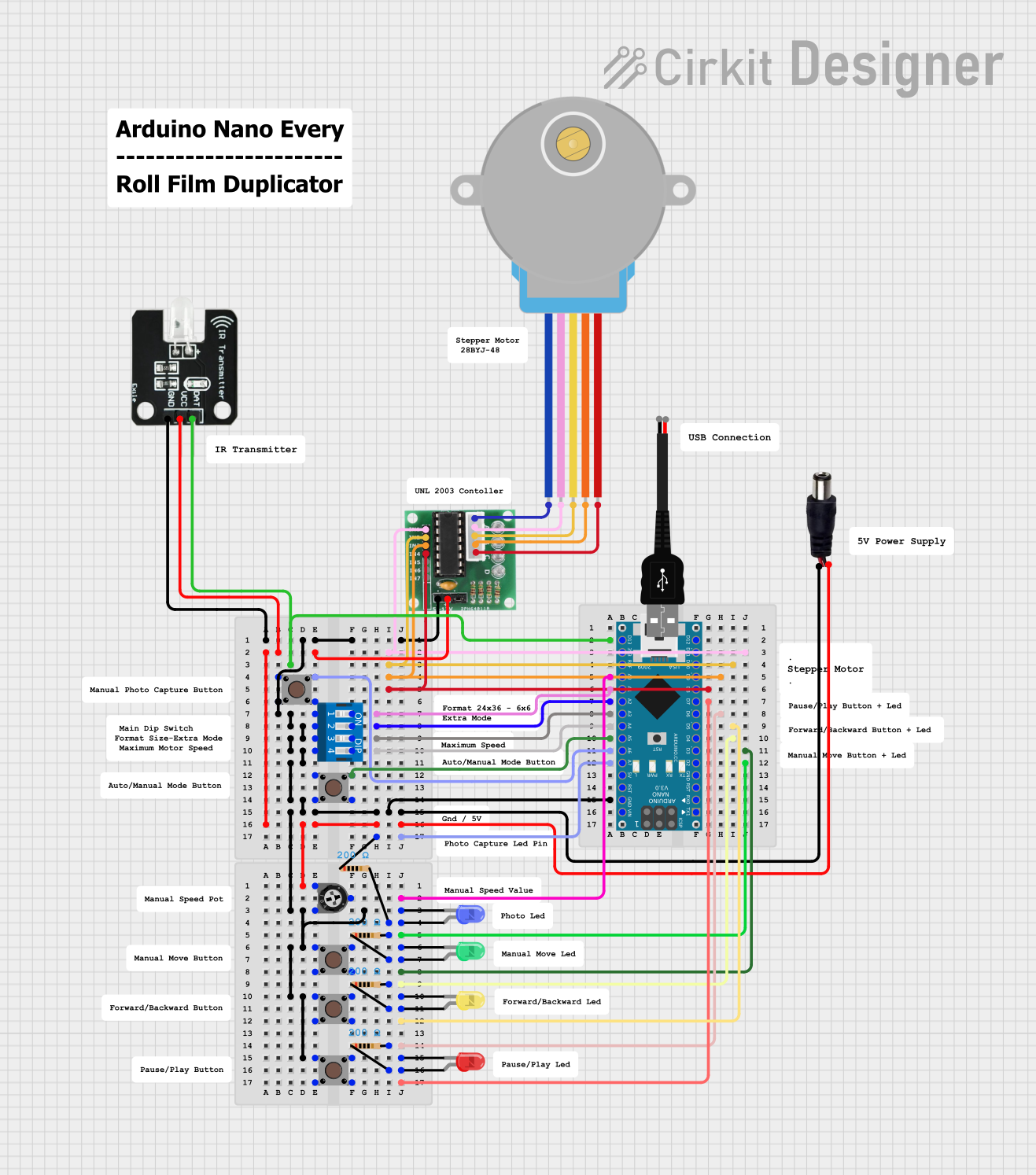
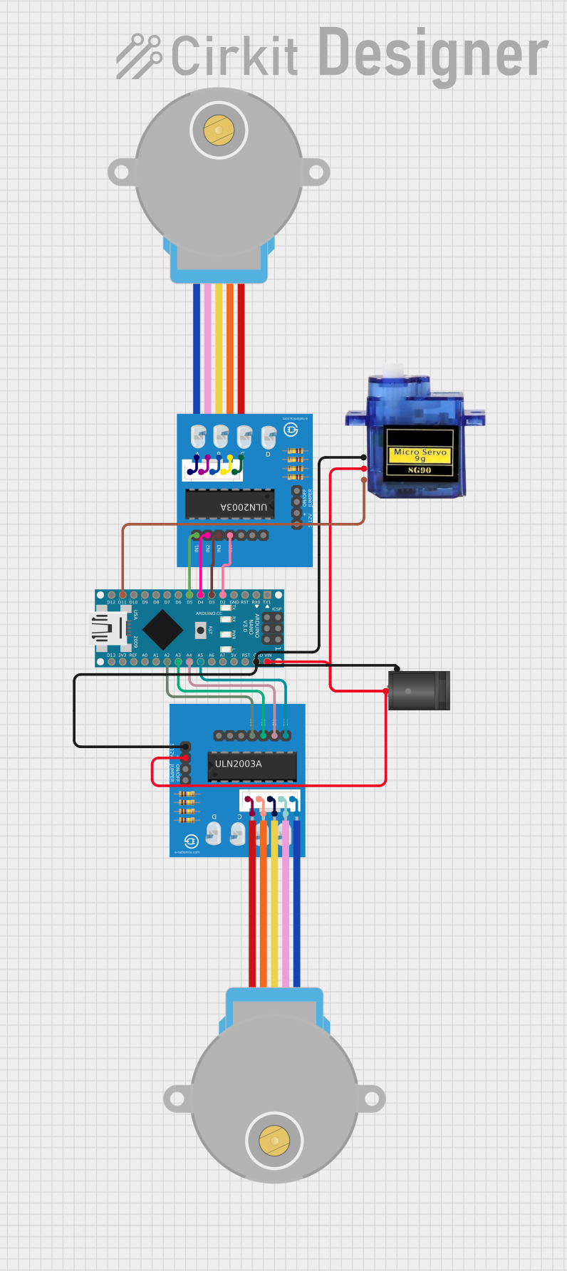
Explore Projects Built with ULN2003A
Technical Specifications
Key Technical Details
- Output Current (per channel): 500 mA
- Output Voltage: 50 V
- Input Voltage: 3.3V to 5V (compatible with most logic families)
- Clamping Diodes: Built-in for inductive load transient suppression
- Package: 16-pin DIP (Dual In-line Package)
Pin Configuration and Descriptions
| Pin Number | Name | Description |
|---|---|---|
| 1-7 | Input 1-7 | Control inputs for each of the seven Darlington pairs |
| 8 | GND | Ground (common for all outputs) |
| 9-15 | Output 1-7 | Outputs for each of the seven Darlington pairs |
| 16 | COM | Common free-wheeling diodes (used for inductive loads) |
Usage Instructions
How to Use the ULN2003A in a Circuit
Connecting Inputs: Connect the input pins (1-7) to the control signals, typically from a microcontroller or logic gates. Ensure that the input voltage levels are compatible with the ULN2003A.
Connecting Outputs: Connect the output pins (9-15) to the loads you wish to drive. Remember that each channel can handle up to 500 mA, but the total package power dissipation should not be exceeded.
Ground and COM Pin: Connect pin 8 (GND) to the system ground. The COM pin (16) should be connected to the positive supply voltage if the internal suppression diodes are used for inductive loads.
Power Supply: Ensure that the power supply for the loads is sufficient to handle the current and voltage requirements.
Heat Dissipation: If driving near the maximum ratings, consider using a heat sink to manage the temperature of the ULN2003A.
Best Practices
- Use a current limiting resistor if the input signal source cannot handle the input current of the ULN2003A.
- When driving inductive loads, make sure to use the built-in diodes by connecting the COM pin to the positive supply voltage to prevent back EMF damage.
- Avoid exceeding the maximum voltage and current ratings to prevent damage to the ULN2003A and the connected loads.
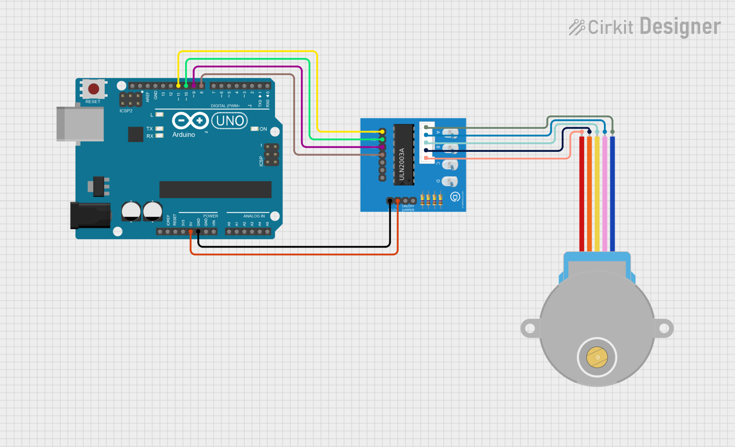
Example Circuit: Driving a Stepper Motor with Arduino UNO
// Define the ULN2003A control pins connected to the Arduino
const int motorPin1 = 2; // IN1 on the ULN2003A
const int motorPin2 = 3; // IN2 on the ULN2003A
const int motorPin3 = 4; // IN3 on the ULN2003A
const int motorPin4 = 5; // IN4 on the ULN2003A

void setup() {
  // Set the motor control pins as outputs
  pinMode(motorPin1, OUTPUT);
  pinMode(motorPin2, OUTPUT);
  pinMode(motorPin3, OUTPUT);
  pinMode(motorPin4, OUTPUT);
}

void loop() {
  // Step through the windings in a sequence to rotate the stepper motor
  digitalWrite(motorPin1, HIGH);
  digitalWrite(motorPin2, LOW);
  digitalWrite(motorPin3, LOW);
  digitalWrite(motorPin4, LOW);
  delay(2); // Wait for 2 milliseconds
  // Repeat for the next steps...
  // Add additional steps to complete the sequence
}
Troubleshooting and FAQs
Common Issues
- Insufficient Load Driving: Ensure that the input signals are at the correct logic level and that the power supply can deliver enough current for the loads.
- Overheating: If the ULN2003A is getting too hot, check if the current through the outputs is within the limit and consider using a heat sink.
- Unexpected Outputs: Verify that the pin connections are correct and that there are no short circuits.
Solutions and Tips
- Input Voltage Levels: Use a logic level converter if the control signal levels are not compatible with the ULN2003A.
- Inductive Loads: Always use the COM pin connection when driving inductive loads to utilize the internal suppression diodes.
- Testing: Test each channel individually before connecting multiple loads to ensure proper operation.
FAQs
Q: Can I drive loads that require more than 500 mA with the ULN2003A? A: No, each channel can only handle up to 500 mA. For higher currents, consider using a more robust driver or paralleling multiple outputs with caution.
Q: Is it necessary to use all seven channels of the ULN2003A? A: No, you can use as many or as few channels as needed for your application.
Q: Can the ULN2003A be used with 3.3V logic levels? A: Yes, the ULN2003A is compatible with 3.3V logic levels, making it suitable for use with many microcontrollers, including those that operate at 3.3V.
Remember to always consult the ULN2003A datasheet for the most accurate and detailed information regarding the operation and limitations of the component.