Cirkit Designer Logo
Cirkit Designer
Your all-in-one circuit design IDE
Home / 
Component Documentation

How to Use SMPS PSU 12V 10A: Examples, Pinouts, and Specs

Image of SMPS PSU 12V 10A
Cirkit Designer LogoDesign with SMPS PSU 12V 10A in Cirkit Designer

Introduction

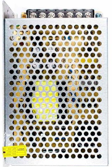
The SMPS PSU 12V 10A is a Switching Mode Power Supply designed to convert AC mains voltage into a stable 12V DC output with a maximum current capacity of 10A. This component is highly efficient and compact, making it ideal for powering a wide range of electronic devices and systems. Its robust design ensures reliable operation in demanding environments.

Explore Projects Built with SMPS PSU 12V 10A

Use Cirkit Designer to design, explore, and prototype these projects online. Some projects support real-time simulation. Click "Open Project" to start designing instantly!
Modular Power Distribution System with Multiple SMPS Units and 120V Outlet
Image of Cellion-Tesla: A project utilizing SMPS PSU 12V 10A in a practical application
This circuit is designed to convert 240V AC power to both 12V and 24V DC outputs using multiple SMPS units. Terminal blocks are used to organize and distribute the power, while a 120V outlet provides additional AC power access. The circuit is likely used for powering various electronic devices that require different voltage levels.
Cirkit Designer LogoOpen Project in Cirkit Designer
12V UPS System with Dual 18650 Li-ion Battery Backup and Voltage Regulation
Image of Power supply: A project utilizing SMPS PSU 12V 10A in a practical application
This circuit is designed to provide an uninterruptible power supply (UPS) system with a 12V DC output. It includes a 12V 5A power supply connected to an AC source through a toggle switch, which charges a pair of 18650 Li-ion batteries via a voltage regulator (XL4016). The UPS module ensures a continuous power supply to the load by switching between the power supply and the battery bank.
Cirkit Designer LogoOpen Project in Cirkit Designer
Industrial Power Distribution and Safety Control System
Image of Control Diagram: A project utilizing SMPS PSU 12V 10A in a practical application
This circuit is designed for power distribution and safety control in an industrial setting. It features a main isolator and circuit breaker for power management, multiple PSUs for 5V, 12V, and 24V outputs, and a safety relay system that interfaces with E-stop buttons and a start switch to control a main contactor, ensuring safe operation and emergency power cut-off capabilities.
Cirkit Designer LogoOpen Project in Cirkit Designer
Dual 5V Power Supply Distribution Circuit with Toggle Switch Control
Image of rfdriver: A project utilizing SMPS PSU 12V 10A in a practical application
This circuit consists of two 5V 5A power supplies connected to an AC wall plug point, providing DC output through a 12-way connector. The ground connections from both power supplies are interconnected and also connected to the ground pins of two toggle switches. The DC outputs from the power supplies are separately connected to different pins on the 12-way connector, with each power supply output being switchable via one of the toggle switches.
Cirkit Designer LogoOpen Project in Cirkit Designer

Explore Projects Built with SMPS PSU 12V 10A

Use Cirkit Designer to design, explore, and prototype these projects online. Some projects support real-time simulation. Click "Open Project" to start designing instantly!
Image of Cellion-Tesla: A project utilizing SMPS PSU 12V 10A in a practical application
Modular Power Distribution System with Multiple SMPS Units and 120V Outlet
This circuit is designed to convert 240V AC power to both 12V and 24V DC outputs using multiple SMPS units. Terminal blocks are used to organize and distribute the power, while a 120V outlet provides additional AC power access. The circuit is likely used for powering various electronic devices that require different voltage levels.
Cirkit Designer LogoOpen Project in Cirkit Designer
Image of Power supply: A project utilizing SMPS PSU 12V 10A in a practical application
12V UPS System with Dual 18650 Li-ion Battery Backup and Voltage Regulation
This circuit is designed to provide an uninterruptible power supply (UPS) system with a 12V DC output. It includes a 12V 5A power supply connected to an AC source through a toggle switch, which charges a pair of 18650 Li-ion batteries via a voltage regulator (XL4016). The UPS module ensures a continuous power supply to the load by switching between the power supply and the battery bank.
Cirkit Designer LogoOpen Project in Cirkit Designer
Image of Control Diagram: A project utilizing SMPS PSU 12V 10A in a practical application
Industrial Power Distribution and Safety Control System
This circuit is designed for power distribution and safety control in an industrial setting. It features a main isolator and circuit breaker for power management, multiple PSUs for 5V, 12V, and 24V outputs, and a safety relay system that interfaces with E-stop buttons and a start switch to control a main contactor, ensuring safe operation and emergency power cut-off capabilities.
Cirkit Designer LogoOpen Project in Cirkit Designer
Image of rfdriver: A project utilizing SMPS PSU 12V 10A in a practical application
Dual 5V Power Supply Distribution Circuit with Toggle Switch Control
This circuit consists of two 5V 5A power supplies connected to an AC wall plug point, providing DC output through a 12-way connector. The ground connections from both power supplies are interconnected and also connected to the ground pins of two toggle switches. The DC outputs from the power supplies are separately connected to different pins on the 12-way connector, with each power supply output being switchable via one of the toggle switches.
Cirkit Designer LogoOpen Project in Cirkit Designer

Common Applications and Use Cases

  • Powering LED strips, modules, and lighting systems
  • Supplying power to microcontrollers, development boards, and sensors
  • Driving DC motors and actuators
  • Providing power for CCTV cameras and security systems
  • General-purpose DC power supply for laboratory and prototyping work

Technical Specifications

The following table outlines the key technical details of the SMPS PSU 12V 10A:

Parameter Specification
Input Voltage Range 100-240V AC, 50/60Hz
Output Voltage 12V DC
Maximum Output Current 10A
Output Power 120W
Efficiency ≥85%
Ripple and Noise ≤120mV
Operating Temperature -10°C to +50°C
Protection Features Overload, Overvoltage, Short Circuit

Pin Configuration and Descriptions

The SMPS PSU 12V 10A typically has the following input and output terminals:

Terminal Label Description
Input 1 L Live AC input (connect to the live wire of mains)
Input 2 N Neutral AC input (connect to the neutral wire)
Input 3 GND Ground (optional, for safety grounding)
Output 1 +V Positive DC output terminal (12V DC)
Output 2 -V Negative DC output terminal (ground for 12V DC)

Usage Instructions

How to Use the Component in a Circuit

  1. Safety First: Ensure the SMPS is disconnected from the mains power before wiring.
  2. Connect the Input Terminals:
    • Connect the L terminal to the live wire of the AC mains.
    • Connect the N terminal to the neutral wire of the AC mains.
    • Optionally, connect the GND terminal to the earth ground for safety.
  3. Connect the Output Terminals:
    • Connect the +V terminal to the positive input of your load or circuit.
    • Connect the -V terminal to the ground or negative input of your load or circuit.
  4. Power On: After verifying all connections, plug the SMPS into the mains power supply and switch it on.
  5. Load Considerations: Ensure the total current drawn by the connected devices does not exceed 10A.

Important Considerations and Best Practices

  • Ventilation: Ensure adequate airflow around the SMPS to prevent overheating.
  • Load Matching: Avoid connecting loads that exceed the maximum power rating (120W).
  • Fuse Protection: Use an appropriate fuse on the input side for added safety.
  • Polarity: Double-check the polarity of the output connections to avoid damaging your devices.
  • Isolation: If used in sensitive circuits, consider additional isolation to prevent noise interference.

Example: Connecting to an Arduino UNO

The SMPS PSU 12V 10A can be used to power an Arduino UNO via a DC-DC step-down converter (buck converter) to step down the 12V to 5V. Below is an example Arduino code to blink an LED when powered by the SMPS:

// Example Arduino code to blink an LED
// Ensure the SMPS output is stepped down to 5V before connecting to the Arduino

const int ledPin = 13; // Pin connected to the onboard LED

void setup() {
  pinMode(ledPin, OUTPUT); // Set the LED pin as an output
}

void loop() {
  digitalWrite(ledPin, HIGH); // Turn the LED on
  delay(1000);                // Wait for 1 second
  digitalWrite(ledPin, LOW);  // Turn the LED off
  delay(1000);                // Wait for 1 second
}

Troubleshooting and FAQs

Common Issues and Solutions

  1. No Output Voltage:

    • Check if the SMPS is properly connected to the AC mains.
    • Verify that the input voltage is within the specified range (100-240V AC).
    • Ensure the load does not exceed the maximum current rating (10A).
  2. Overheating:

    • Ensure proper ventilation and avoid placing the SMPS in enclosed spaces.
    • Check if the connected load is within the power rating (120W).
  3. Noise or Ripple in Output:

    • Use additional filtering capacitors at the output terminals.
    • Ensure the load is not causing excessive current spikes.
  4. SMPS Not Powering On:

    • Verify the fuse on the input side (if used) is not blown.
    • Check for any visible damage or burnt components.

FAQs

Q1: Can I use this SMPS to power a 5V device?
A1: Yes, but you will need a DC-DC step-down converter to reduce the 12V output to 5V.

Q2: Is the SMPS safe to use with sensitive electronics?
A2: Yes, but for highly sensitive devices, consider adding additional filtering or isolation to minimize noise.

Q3: What happens if I exceed the 10A current limit?
A3: The SMPS has built-in overload protection and will shut down to prevent damage. Reduce the load and restart the SMPS.

Q4: Can I use this SMPS outdoors?
A4: This SMPS is not weatherproof. Use it in a dry, indoor environment or within a weatherproof enclosure.