How to Use Adafruit MicroSD card breakout board: Examples, Pinouts, and Specs
Introduction
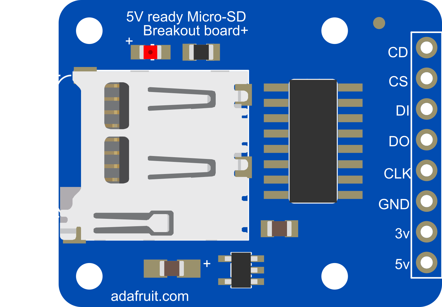
The Adafruit MicroSD Card Breakout Board is a compact interface for microSD cards, providing an easy method to add data storage capabilities to your electronic projects. It operates over a Serial Peripheral Interface (SPI) for communication with microcontrollers such as the Arduino UNO. This breakout board is commonly used in data logging, MP3 players, and portable scientific instruments where data storage is essential.
Explore Projects Built with Adafruit MicroSD card breakout board

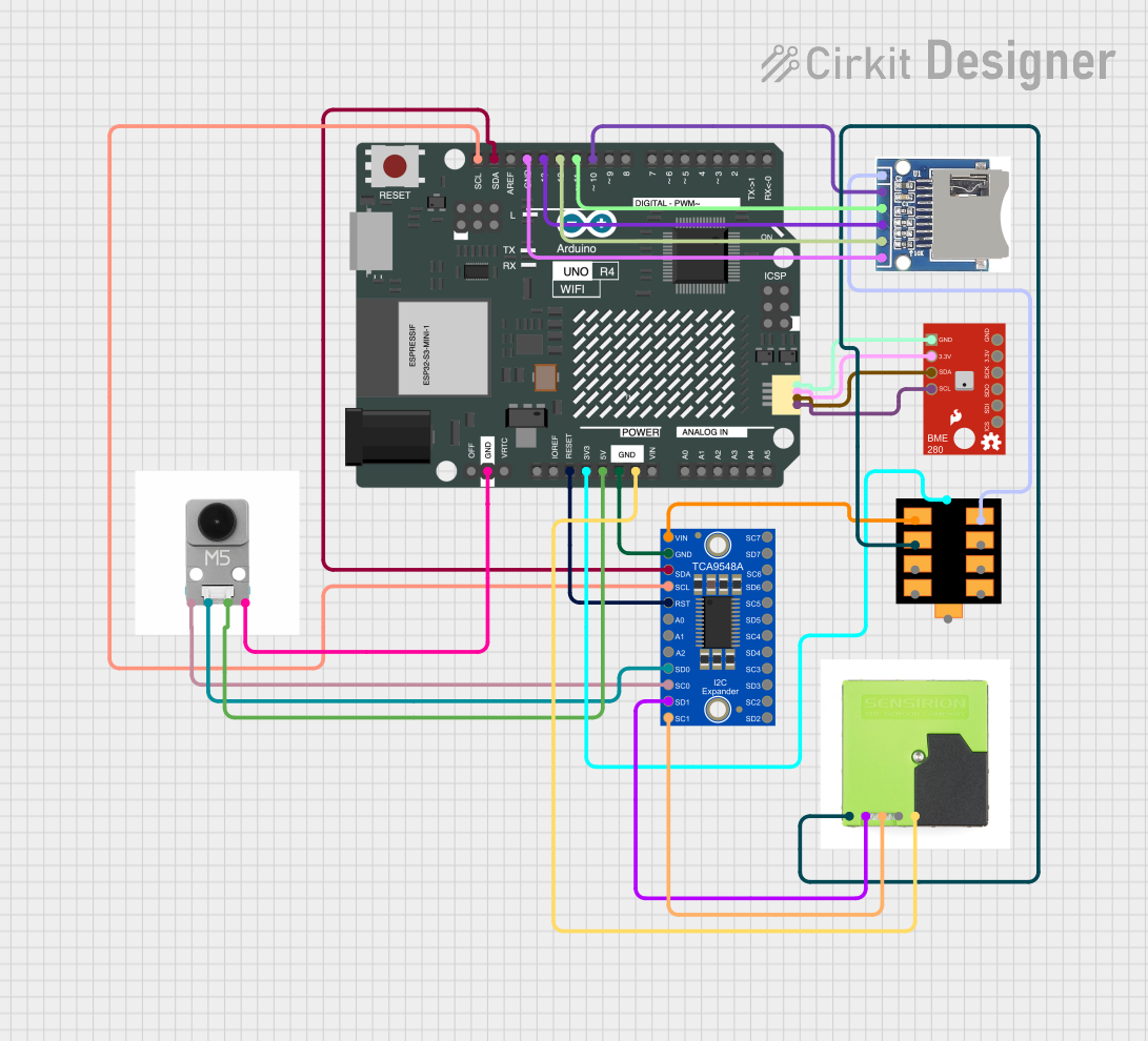
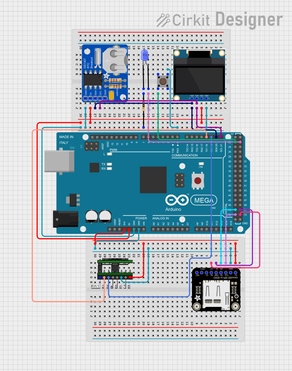
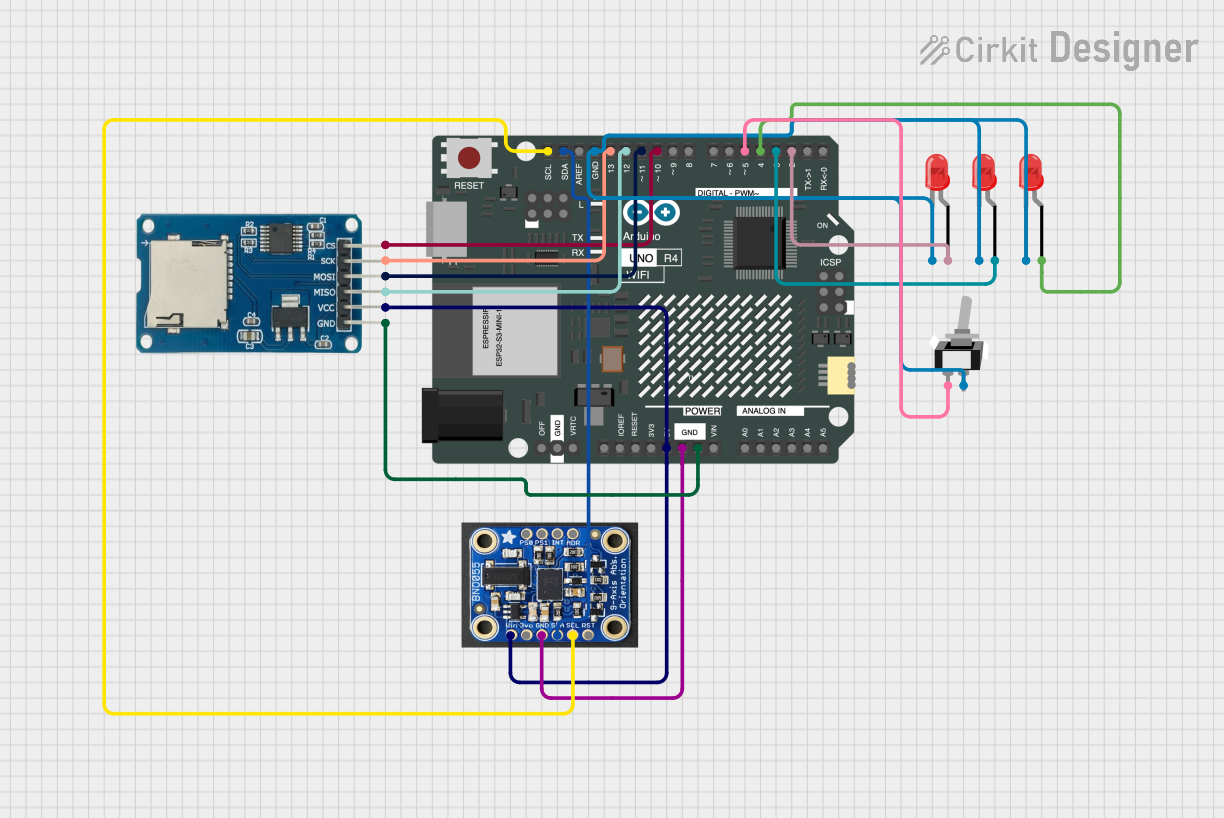
Explore Projects Built with Adafruit MicroSD card breakout board
Common Applications and Use Cases
- Data logging (temperature, humidity, pressure, etc.)
- MP3 and multimedia file storage
- Portable scientific instruments data storage
- Configuration or settings files for electronic devices
- Storing images for display on LCD screens
Technical Specifications
Key Technical Details
- Voltage: 3.3V to 5V power and logic level compatible
- Current: 0.5mA idle, 100mA active (maximum)
- Data Transfer Protocol: SPI (Serial Peripheral Interface)
- Supported microSD Card Types: microSD, microSDHC (up to 32GB)
Pin Configuration and Descriptions
| Pin Name | Description |
|---|---|
| CS | Chip Select, active low |
| DI | Data In, SPI MOSI (Master Out Slave In) |
| DO | Data Out, SPI MISO (Master In Slave Out) |
| CLK | SPI Clock |
| GND | Ground |
| VCC | Power Supply (3.3V to 5V) |
| CD | Card Detect (optional, not always used) |
Usage Instructions
How to Use the Component in a Circuit
- Power Connections: Connect VCC to 3.3V or 5V power supply and GND to the ground of your system.
- SPI Connections: Connect the SPI pins (CS, DI, DO, CLK) to the corresponding SPI pins on your microcontroller.
- Card Detection (Optional): Connect the CD pin to a digital input if card detection functionality is needed.
Important Considerations and Best Practices
- Use a level shifter if your microcontroller operates at a different logic level than the microSD card.
- Format the microSD card to FAT16 or FAT32 file system before use.
- Ensure that the microSD card is inserted correctly before powering up the circuit.
- Use a pull-up resistor on the CS pin to prevent unintended SPI communication.
Example Code for Arduino UNO
#include <SPI.h>
#include <SD.h>

// Pin configuration
const int chipSelect = 10; // CS pin connected to digital pin 10

void setup() {
  Serial.begin(9600);
  while (!Serial) {
    ; // Wait for serial port to connect.
  }

  Serial.print("Initializing SD card...");

  // Ensure CS pin is set to output
  pinMode(chipSelect, OUTPUT);

  // Check for successful card initialization
  if (!SD.begin(chipSelect)) {
    Serial.println("Card failed, or not present");
    // Don't continue with setup if the card failed to initialize
    while (1);
  }
  Serial.println("Card initialized.");
}

void loop() {
  // Main code to read/write from/to the SD card
}
Troubleshooting and FAQs
Common Issues Users Might Face
- Card Not Detected: Ensure the card is inserted correctly and the CS pin is properly connected.
- Read/Write Errors: Check if the microSD card is formatted correctly and not corrupted.
- Communication Errors: Verify that the SPI connections are secure and the correct SPI port is used in the code.
Solutions and Tips for Troubleshooting
- Reformat the microSD card on a computer to ensure it's clean and properly formatted.
- Use a multimeter to check the continuity of the SPI connections.
- If using a 5V microcontroller, ensure that a level shifter is used to avoid damaging the microSD card.
FAQs
Q: Can I use a microSD card larger than 32GB? A: The breakout board supports microSDHC cards, which go up to 32GB. Using larger cards may require a different file system and is not guaranteed to work.
Q: Do I need to use the CD (Card Detect) pin? A: The CD pin is optional. It can be used to detect the presence of a card but is not required for basic operation.
Q: Can I hot-swap the microSD card while the system is powered? A: Hot-swapping is not recommended as it may cause data corruption or damage to the card. Always power down the system before inserting or removing the card.