
How to Use Self-Lock Push Button Switch: Examples, Pinouts, and Specs
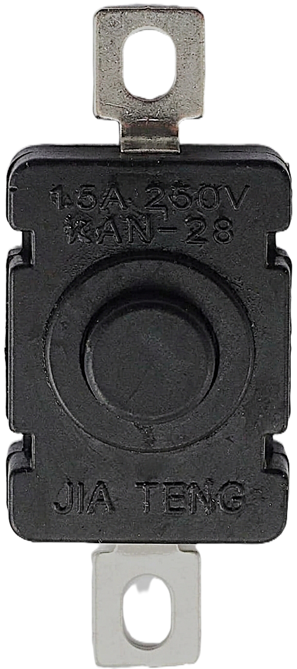
 Design with Self-Lock Push Button Switch in Cirkit Designer
Introduction
The Self-Lock Push Button Switch is a mechanical switch designed to maintain its position after being pressed. Unlike momentary switches, which return to their default state when released, this switch "locks" into place, toggling between on and off states with each press. This functionality makes it ideal for applications requiring a persistent state without continuous user interaction.
Explore Projects Built with Self-Lock Push Button Switch
 Open Project in Cirkit Designer
 Open Project in Cirkit Designer
 Open Project in Cirkit Designer
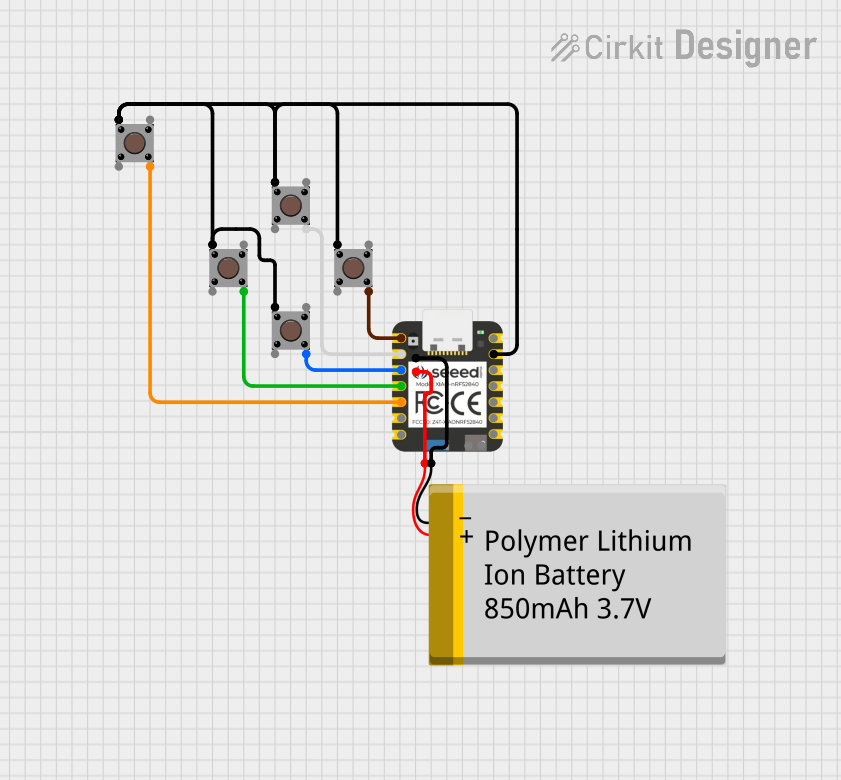 Open Project in Cirkit Designer
Explore Projects Built with Self-Lock Push Button Switch
Open Project in Cirkit DesignerOpen Project in Cirkit DesignerOpen Project in Cirkit DesignerOpen Project in Cirkit DesignerCommon Applications and Use Cases
- Power toggling for electronic devices
- Mode selection in control panels
- On/off control for lighting systems
- DIY electronics and prototyping projects
- Industrial machinery controls
Technical Specifications
Below are the key technical details for the Self-Lock Push Button Switch:
| Parameter | Value |
|---|---|
| Operating Voltage | 3V to 250V (AC/DC, depending on model) |
| Operating Current | 0.5A to 3A (varies by model) |
| Contact Resistance | ≤ 50 mΩ |
| Insulation Resistance | ≥ 100 MΩ |
| Mechanical Durability | ≥ 50,000 cycles |
| Mounting Type | Panel mount or PCB mount |
| Switch Type | Latching (self-locking) |
| Dimensions | Varies by model (e.g., 12mm diameter for panel mount) |
Pin Configuration and Descriptions
The Self-Lock Push Button Switch typically has two or more terminals. Below is a general description of the pin configuration:
| Pin | Description |
|---|---|
| Pin 1 | Common terminal (COM) - Connects to the power source or load. |
| Pin 2 | Normally Open (NO) - Connects to the load when the switch is pressed. |
| Pin 3* | Normally Closed (NC) - Disconnects from the load when the switch is pressed. (*Optional, depending on model) |
Note: Some models may only have two pins (COM and NO). Always refer to the datasheet for your specific switch model.
Usage Instructions
How to Use the Component in a Circuit
- Identify the Terminals: Determine the COM, NO, and NC terminals using the datasheet or a multimeter.
- Connect the Circuit:
- For a simple on/off application, connect the power source to the COM terminal and the load to the NO terminal.
- If using the NC terminal, the load will remain powered until the switch is pressed.
- Mount the Switch: Secure the switch to a panel or PCB as required.
- Test the Circuit: Press the button to toggle the state of the connected load.
Important Considerations and Best Practices
- Voltage and Current Ratings: Ensure the switch's ratings match your circuit's requirements to avoid damage.
- Debouncing: Mechanical switches may produce noise or "bouncing" when toggled. Use a capacitor or software debounce logic to mitigate this.
- Mounting: For panel-mounted switches, ensure the mounting hole matches the switch's dimensions.
- Safety: When working with high voltages, ensure proper insulation and follow safety guidelines.
Example: Connecting to an Arduino UNO
The Self-Lock Push Button Switch can be used with an Arduino UNO for toggling an LED. Below is an example circuit and code:
Circuit Diagram
- Connect the COM terminal of the switch to GND on the Arduino.
- Connect the NO terminal to digital pin 2 on the Arduino.
- Connect an LED to digital pin 13 with a 220Ω resistor in series.
Arduino Code
// Self-Lock Push Button Switch Example
// Toggles an LED on pin 13 when the switch is pressed.

const int buttonPin = 2;  // Pin connected to the switch's NO terminal
const int ledPin = 13;    // Pin connected to the LED
bool ledState = false;    // Variable to store the LED state

void setup() {
  pinMode(buttonPin, INPUT_PULLUP); // Set button pin as input with pull-up resistor
  pinMode(ledPin, OUTPUT);         // Set LED pin as output
}

void loop() {
  static bool lastButtonState = HIGH; // Store the last button state
  bool currentButtonState = digitalRead(buttonPin); // Read the button state

  // Check if the button state has changed
  if (currentButtonState == LOW && lastButtonState == HIGH) {
    ledState = !ledState; // Toggle the LED state
    digitalWrite(ledPin, ledState); // Update the LED
    delay(50); // Debounce delay
  }

  lastButtonState = currentButtonState; // Update the last button state
}
Note: The
INPUT_PULLUPmode is used to simplify the circuit by eliminating the need for an external pull-up resistor.
Troubleshooting and FAQs
Common Issues Users Might Face
- Switch Doesn't Toggle:
- Check the wiring and ensure the correct terminals are connected.
- Verify that the switch is not damaged or worn out.
- LED Flickers or Behaves Erratically:
- This may be caused by switch bouncing. Add a debounce circuit or implement debounce logic in your code.
- Switch Feels Stuck:
- Ensure the switch is not physically obstructed or damaged. Clean the switch if necessary.
Solutions and Tips for Troubleshooting
- Use a multimeter to test the continuity of the switch terminals.
- Double-check the voltage and current ratings to ensure compatibility with your circuit.
- If the switch is not functioning as expected, consult the manufacturer's datasheet for additional details.
FAQ: Can I use this switch for high-power applications? Answer: Yes, but only if the switch's voltage and current ratings meet the requirements of your application. For higher power, consider using the switch to control a relay.
This concludes the documentation for the Self-Lock Push Button Switch.