How to Use 120mm Fan 12V DC 3 Pin with Tach: Examples, Pinouts, and Specs

Documentation for Corsair 120mm Fan 12V DC 3-Pin with Tach (Part ID: 4000D)
1. Introduction
The Corsair 120mm Fan 12V DC 3-Pin with Tach (Part ID: 4000D) is a high-performance cooling fan designed to provide efficient airflow for electronic devices and computer systems. With its 120mm size, 12V DC operation, and 3-pin connector, this fan is ideal for maintaining optimal temperatures in computer cases, power supplies, and other electronic enclosures. The integrated tachometer (speed monitoring) allows users to monitor the fan's RPM (revolutions per minute) for precise control and diagnostics.
Common Applications:
- Cooling computer cases, CPUs, and GPUs
- Enhancing airflow in power supplies and electronic enclosures
- Preventing overheating in custom electronics projects
- General-purpose cooling for robotics and DIY projects
2. Technical Specifications
The following table outlines the key technical details of the Corsair 120mm Fan:
| Parameter | Specification |
|---|---|
| Manufacturer | Corsair |
| Part ID | 4000D |
| Fan Size | 120mm x 120mm x 25mm |
| Operating Voltage | 12V DC |
| Operating Current | 0.25A (typical) |
| Power Consumption | 3W (typical) |
| Connector Type | 3-pin (Power, Ground, Tachometer) |
| Speed Range | 800 - 1500 RPM |
| Airflow | 52 CFM (Cubic Feet per Minute) |
| Noise Level | 25 dBA (maximum) |
| Bearing Type | Hydraulic Bearing |
| Lifespan | 40,000 hours (at 25°C) |
Pin Configuration and Descriptions
The Corsair 120mm Fan features a 3-pin connector. The pinout is as follows:
| Pin Number | Name | Description |
|---|---|---|
| 1 | Power (+) | Positive voltage input (12V DC) |
| 2 | Ground (-) | Ground connection |
| 3 | Tachometer | Outputs a signal proportional to fan speed (RPM) |
3. Usage Instructions
Connecting the Fan to a Circuit
- Power Supply: Connect the fan's power pin (Pin 1) to a 12V DC power source. Ensure the power supply can provide at least 0.25A of current.
- Ground: Connect the ground pin (Pin 2) to the ground of your circuit or power supply.
- Tachometer (Optional): Connect the tachometer pin (Pin 3) to a microcontroller or monitoring device to read the fan's RPM. The tachometer signal is a pulsed output, with two pulses per revolution.
Important Considerations:
- Voltage Range: Do not exceed the rated 12V DC input to avoid damaging the fan.
- Mounting: Use the provided mounting holes to securely attach the fan to your device or enclosure. Ensure proper airflow direction by observing the fan's airflow indicator (usually marked on the fan housing).
- Tachometer Signal: The tachometer output is an open-drain signal. Use a pull-up resistor (typically 10kΩ) when connecting to a microcontroller.
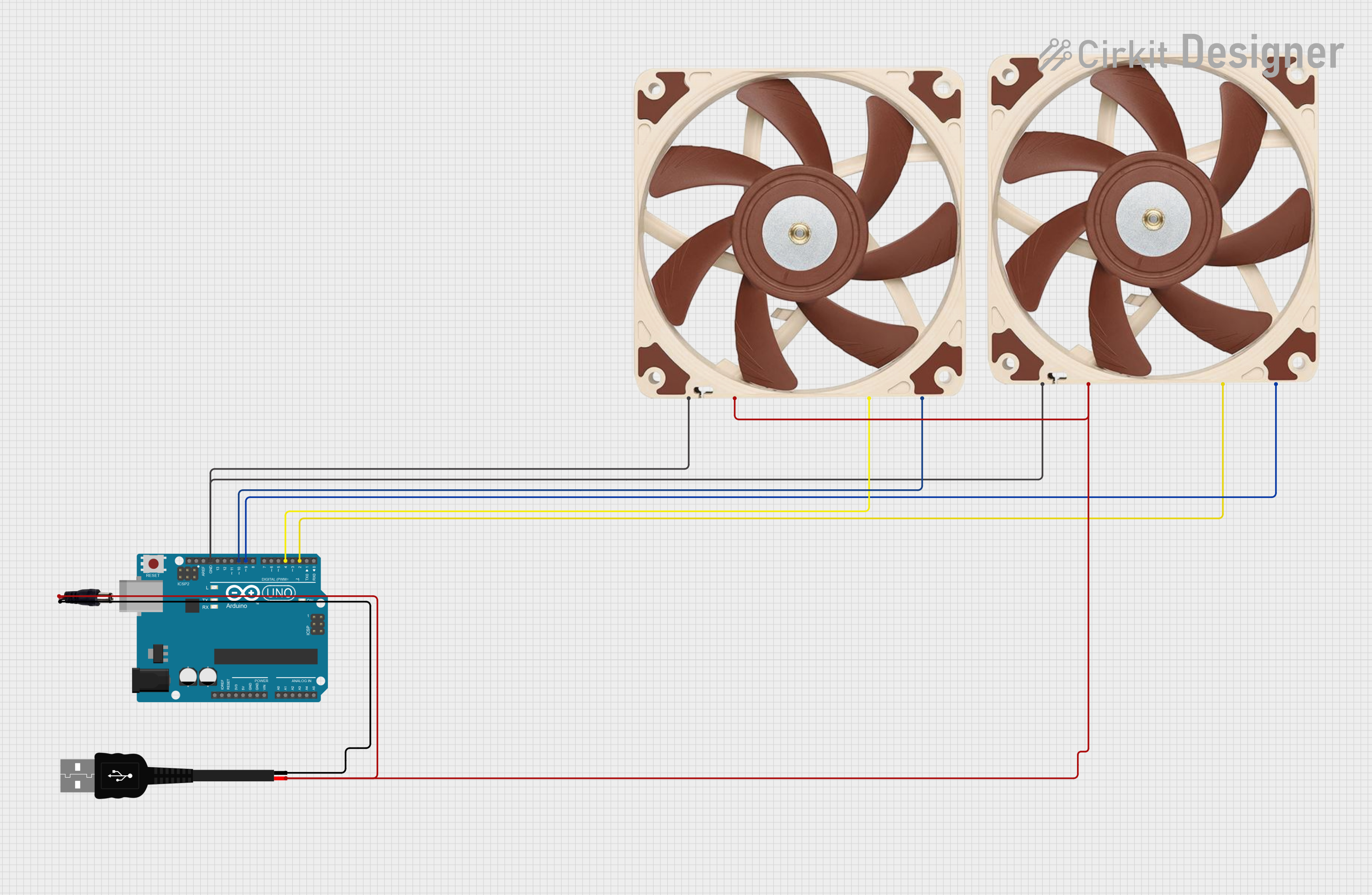
4. Example: Using the Fan with an Arduino UNO
The following example demonstrates how to connect the Corsair 120mm Fan to an Arduino UNO to monitor its RPM using the tachometer pin.
Circuit Diagram:
- Pin 1 (Power): Connect to the Arduino's 12V power supply.
- Pin 2 (Ground): Connect to the Arduino's GND.
- Pin 3 (Tachometer): Connect to Arduino digital pin 2 with a 10kΩ pull-up resistor to 5V.
Arduino Code:
// Corsair 120mm Fan RPM Monitoring with Arduino UNO
// Connect the fan's tachometer pin to Arduino digital pin 2
// Use a 10kΩ pull-up resistor between the tachometer pin and 5V

const int tachPin = 2;  // Tachometer signal pin
volatile int pulseCount = 0;  // Count of tachometer pulses

void pulseCounter() {
  // Interrupt service routine to count tachometer pulses
  pulseCount++;
}

void setup() {
  pinMode(tachPin, INPUT_PULLUP);  // Set tachometer pin as input with pull-up
  attachInterrupt(digitalPinToInterrupt(tachPin), pulseCounter, FALLING);
  Serial.begin(9600);  // Initialize serial communication
}

void loop() {
  // Calculate RPM based on pulse count
  noInterrupts();  // Disable interrupts to read pulseCount safely
  int pulses = pulseCount;
  pulseCount = 0;  // Reset pulse count
  interrupts();  // Re-enable interrupts

  // Each revolution produces 2 pulses, so RPM = (pulses / 2) * 60
  int rpm = (pulses / 2) * 60;

  // Print RPM to the Serial Monitor
  Serial.print("Fan RPM: ");
  Serial.println(rpm);

  delay(1000);  // Update RPM every second
}
Notes:
- Ensure the Arduino is powered by a 12V DC source to power the fan.
- The tachometer signal is read using an interrupt for accurate pulse counting.
5. Troubleshooting and FAQs
Common Issues and Solutions:
| Issue | Possible Cause | Solution |
|---|---|---|
| Fan does not spin | No power or incorrect voltage | Ensure 12V DC is supplied to the fan. |
| Fan spins but no RPM reading | Tachometer not connected or pull-up missing | Check tachometer connection and add pull-up. |
| Fan is noisy | Dust or debris in the fan | Clean the fan blades and housing. |
| Fan speed is inconsistent | Voltage fluctuations | Use a stable 12V DC power supply. |
FAQs:
Can I control the fan speed?
- This fan does not support PWM speed control. However, you can adjust the voltage (e.g., using a variable power supply) to control the speed.
What is the purpose of the tachometer pin?
- The tachometer pin outputs a signal proportional to the fan's speed, allowing you to monitor its RPM.
Can I use this fan with a 5V power supply?
- No, the fan is designed to operate at 12V DC. Using a lower voltage may prevent the fan from spinning or reduce its performance.
How do I clean the fan?
- Use compressed air or a soft brush to remove dust and debris. Avoid using water or harsh chemicals.
This documentation provides all the necessary details to use the Corsair 120mm Fan 12V DC 3-Pin with Tach effectively in your projects. For further assistance, refer to the manufacturer's datasheet or contact Corsair support.
Explore Projects Built with 120mm Fan 12V DC 3 Pin with Tach


Explore Projects Built with 120mm Fan 12V DC 3 Pin with Tach