
How to Use uln2003: Examples, Pinouts, and Specs
 Design with uln2003 in Cirkit Designer
Introduction
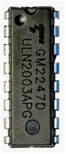
The ULN2003 is a high-voltage, high-current Darlington transistor array. It consists of seven NPN Darlington pairs, each capable of driving high-current loads. This component is widely used for interfacing low-power digital circuits, such as microcontrollers, with high-power devices like relays, stepper motors, lamps, and solenoids. Its built-in flyback diodes make it particularly suitable for inductive loads, ensuring safe operation and protecting the circuit from voltage spikes.
Explore Projects Built with uln2003
 Open Project in Cirkit Designer
 Open Project in Cirkit Designer
 Open Project in Cirkit Designer
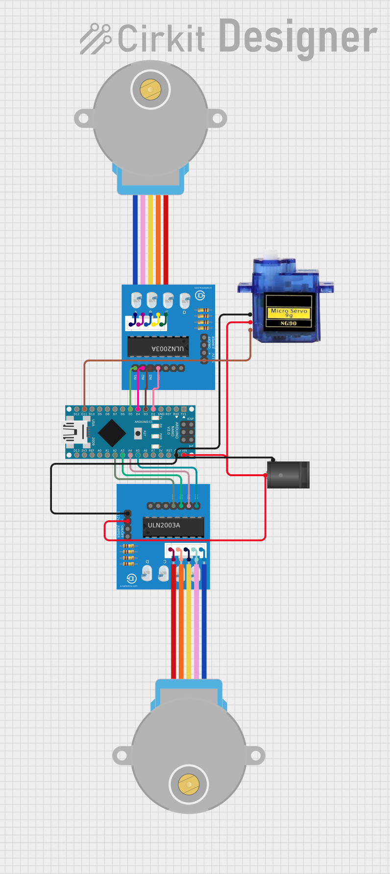 Open Project in Cirkit Designer
Explore Projects Built with uln2003
Open Project in Cirkit DesignerOpen Project in Cirkit DesignerOpen Project in Cirkit DesignerOpen Project in Cirkit DesignerCommon Applications
- Driving stepper motors
- Controlling relays
- Powering LED arrays
- Interfacing microcontrollers with high-power devices
- Industrial automation systems
Technical Specifications
The ULN2003 is designed to handle high voltages and currents while providing ease of use in various applications. Below are its key technical details:
Key Specifications
| Parameter | Value |
|---|---|
| Supply Voltage (VCE) | Up to 50V |
| Output Current (per pin) | 500mA (maximum) |
| Total Current (all pins) | 2.5A (maximum) |
| Input Voltage (VIH) | 2.4V (minimum for HIGH state) |
| Output Saturation Voltage | 1.6V (at 350mA output current) |
| Flyback Diodes | Built-in for inductive loads |
| Package Type | DIP-16, SOIC-16 |
| Operating Temperature | -20°C to +85°C |
Pin Configuration
The ULN2003 has 16 pins, as described in the table below:
| Pin Number | Name | Description |
|---|---|---|
| 1-7 | Input 1-7 | Inputs for controlling the corresponding outputs (active HIGH) |
| 8 | GND | Ground connection |
| 9-15 | Output 1-7 | Outputs for driving loads (active LOW) |
| 16 | COM (Common) | Common cathode for flyback diodes; connect to the positive supply of loads |
Usage Instructions
The ULN2003 is straightforward to use in circuits. Below are the steps and considerations for proper usage:
How to Use the ULN2003
- Connect the Inputs: Connect the input pins (1-7) to the digital outputs of your microcontroller or control circuit. A HIGH signal on an input pin will activate the corresponding output pin.
- Connect the Outputs: Connect the output pins (9-15) to the negative terminals of your loads (e.g., relays, motors, or LEDs).
- Flyback Diode Connection: For inductive loads, connect the COM pin (16) to the positive supply voltage of the load. This ensures the built-in flyback diodes protect the circuit from voltage spikes.
- Ground Connection: Connect the GND pin (8) to the ground of your circuit.
- Power Supply: Ensure the load's power supply voltage and current are within the ULN2003's specifications.
Example: Controlling a Stepper Motor with Arduino UNO
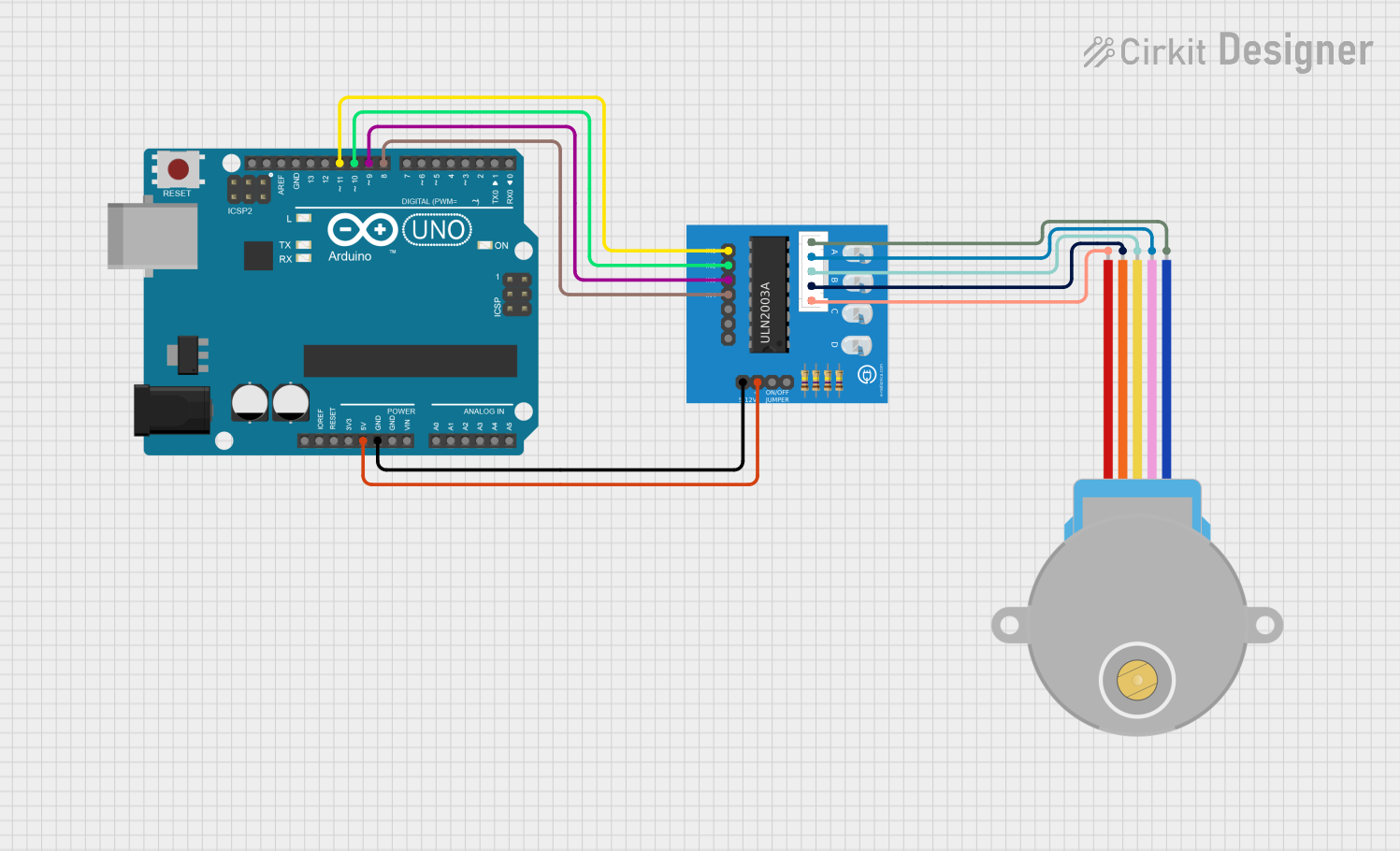
The ULN2003 is commonly used to drive stepper motors. Below is an example of how to control a 28BYJ-48 stepper motor using an Arduino UNO and the ULN2003.
Circuit Connections
- Connect the stepper motor's four control wires to the ULN2003's output pins (e.g., Output 1-4).
- Connect the ULN2003's input pins (Input 1-4) to Arduino digital pins (e.g., D8-D11).
- Connect the COM pin to the motor's power supply (e.g., 5V).
- Connect the GND pin to the Arduino's ground.
Arduino Code
// Include the Stepper library
#include <Stepper.h>

// Define the number of steps per revolution for the stepper motor
#define STEPS_PER_REV 2048

// Initialize the Stepper library with the ULN2003 pins
Stepper stepper(STEPS_PER_REV, 8, 10, 9, 11);

void setup() {
  // Set the speed of the stepper motor (in RPM)
  stepper.setSpeed(15);
}

void loop() {
  // Rotate the motor one full revolution clockwise
  stepper.step(STEPS_PER_REV);
  delay(1000); // Wait for 1 second

  // Rotate the motor one full revolution counterclockwise
  stepper.step(-STEPS_PER_REV);
  delay(1000); // Wait for 1 second
}
Best Practices
- Always check the current and voltage ratings of your load to ensure they are within the ULN2003's limits.
- Use proper decoupling capacitors in your circuit to reduce noise and improve stability.
- For inductive loads, ensure the COM pin is connected to the load's positive supply to utilize the built-in flyback diodes.
Troubleshooting and FAQs
Common Issues and Solutions
Problem: The load is not turning on.
- Solution: Verify that the input signal is HIGH (at least 2.4V). Check the connections between the ULN2003 and the load.
Problem: The ULN2003 is overheating.
- Solution: Ensure the total current drawn by all outputs does not exceed 2.5A. Use a heatsink if necessary.
Problem: Voltage spikes are damaging the circuit.
- Solution: Confirm that the COM pin is connected to the positive supply of the inductive load to activate the flyback diodes.
Problem: The stepper motor is not rotating correctly.
- Solution: Double-check the wiring between the ULN2003 and the stepper motor. Ensure the step sequence in the code matches the motor's wiring.
FAQs
Can the ULN2003 drive a DC motor? Yes, the ULN2003 can drive small DC motors, but ensure the motor's current and voltage are within the ULN2003's limits.
Do I need external diodes for inductive loads? No, the ULN2003 has built-in flyback diodes for this purpose.
What is the maximum input voltage for the ULN2003? The input voltage should not exceed the logic HIGH threshold, typically 5V for most microcontrollers.
By following this documentation, you can effectively use the ULN2003 in your projects to control high-power devices with ease and reliability.