How to Use UPS HAT (D): Examples, Pinouts, and Specs
Introduction
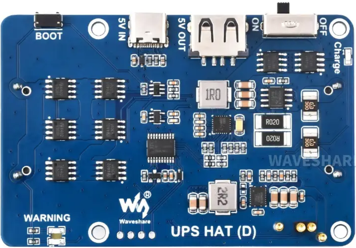
The UPS HAT (D) by Waveshare is an add-on board designed for Raspberry Pi devices to provide uninterruptible power supply functionality. It ensures continuous operation during power outages by utilizing a rechargeable lithium battery. This HAT is particularly useful for applications requiring high reliability, such as IoT devices, servers, or remote monitoring systems.
Explore Projects Built with UPS HAT (D)


Explore Projects Built with UPS HAT (D)
Common Applications and Use Cases
- IoT Devices: Ensures uninterrupted operation of Raspberry Pi-based IoT systems.
- Data Logging: Prevents data loss during unexpected power failures.
- Remote Monitoring: Keeps remote systems operational during power outages.
- Home Automation: Provides backup power for critical home automation tasks.
- Portable Projects: Enables mobility by acting as a power source for Raspberry Pi.
Technical Specifications
The UPS HAT (D) is equipped with advanced features to ensure reliable power delivery and monitoring. Below are the key technical details:
Key Technical Details
| Parameter | Specification |
|---|---|
| Input Voltage | 5V (via micro-USB or GPIO header) |
| Output Voltage | 5V (regulated) |
| Battery Type | Lithium-ion or Lithium-polymer |
| Battery Capacity | Supports batteries up to 5000mAh |
| Charging Current | 1A (max) |
| Communication Interface | I2C |
| Dimensions | 65mm × 56mm |
| Weight | ~30g (excluding battery) |
Pin Configuration and Descriptions
The UPS HAT (D) connects to the Raspberry Pi via the GPIO header. Below is the pin configuration:
| Pin | Name | Description |
|---|---|---|
| 1 | 3.3V | Power supply for I2C communication |
| 3 | SDA | I2C data line |
| 5 | SCL | I2C clock line |
| 6 | GND | Ground |
| 2, 4 | 5V | Power output to Raspberry Pi |
| 7 | INT | Interrupt pin for battery status alerts |
Usage Instructions
The UPS HAT (D) is easy to integrate with Raspberry Pi. Follow the steps below to set it up and use it effectively:
Step 1: Hardware Setup
- Attach the HAT: Align the UPS HAT (D) with the Raspberry Pi GPIO header and gently press it into place.
- Connect the Battery: Attach a compatible lithium battery to the JST connector on the HAT.
- Power Input: Optionally, connect a 5V power source to the micro-USB port or GPIO header.
Step 2: Software Setup
- Enable I2C: On your Raspberry Pi, enable I2C communication using
raspi-config:sudo raspi-configInterfacing Options > I2Cand enable it. - Install Required Libraries: Install the Python
smbuslibrary for I2C communication:sudo apt-get update sudo apt-get install python3-smbus i2c-tools - Verify I2C Connection: Check if the UPS HAT (D) is detected on the I2C bus:
You should see the device address (e.g.,i2cdetect -y 10x36) in the output.
Step 3: Example Code
The following Python code demonstrates how to read the battery voltage and percentage from the UPS HAT (D):
import smbus
import time
Initialize I2C bus
bus = smbus.SMBus(1) # Use I2C bus 1 on Raspberry Pi DEVICE_ADDRESS = 0x36 # Default I2C address of UPS HAT (D)
def read_voltage(): # Read raw voltage data (2 bytes) raw = bus.read_word_data(DEVICE_ADDRESS, 0x02) # Swap byte order and convert to voltage voltage = ((raw & 0xFF) << 8 | (raw >> 8)) * 1.25 / 1000 return voltage
def read_capacity(): # Read raw capacity data (2 bytes) raw = bus.read_word_data(DEVICE_ADDRESS, 0x04) # Swap byte order and convert to percentage capacity = ((raw & 0xFF) << 8 | (raw >> 8)) / 256 return capacity
while True: voltage = read_voltage() capacity = read_capacity() print(f"Battery Voltage: {voltage:.2f}V") print(f"Battery Capacity: {capacity:.2f}%") time.sleep(5) # Wait 5 seconds before the next reading
Important Considerations and Best Practices
- Battery Selection: Use only compatible lithium-ion or lithium-polymer batteries with appropriate capacity and voltage ratings.
- Ventilation: Ensure proper ventilation to prevent overheating during charging.
- Shutdown Procedure: Use the Raspberry Pi's shutdown command before disconnecting the UPS HAT to avoid data corruption.
- Firmware Updates: Check the Waveshare website for firmware updates or additional resources.
Troubleshooting and FAQs
Common Issues and Solutions
HAT Not Detected on I2C Bus:
- Ensure I2C is enabled in
raspi-config. - Verify the HAT is properly seated on the GPIO header.
- Check the I2C address using
i2cdetect -y 1.
- Ensure I2C is enabled in
Battery Not Charging:
- Confirm the battery is connected securely to the JST connector.
- Ensure the input power supply provides sufficient current (at least 1A).
Raspberry Pi Shuts Down Unexpectedly:
- Check the battery capacity and charge level.
- Verify the HAT is supplying 5V to the Raspberry Pi.
Incorrect Voltage or Capacity Readings:
- Ensure the Python script is using the correct I2C address.
- Verify the battery is functioning properly.
FAQs
Q: Can I use the UPS HAT (D) with other single-board computers?
A: While designed for Raspberry Pi, the UPS HAT (D) can be used with other devices that support 5V input and I2C communication. However, software compatibility may vary.
Q: What is the maximum runtime on battery power?
A: The runtime depends on the battery capacity and the power consumption of your Raspberry Pi. For example, a 3000mAh battery can power a Raspberry Pi 4 (idle) for approximately 2-3 hours.
Q: Is it safe to leave the HAT connected to power continuously?
A: Yes, the UPS HAT (D) includes overcharge protection to ensure safe operation during continuous use.
Q: Can I monitor the battery status programmatically?
A: Yes, the HAT provides battery voltage and capacity data via I2C, which can be accessed using the example Python code provided above.