How to Use Battery holder AAx6: Examples, Pinouts, and Specs
Introduction
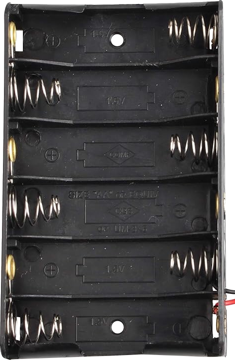
A 6 AA battery holder is a simple yet essential component in the world of electronics. It is designed to hold six AA batteries in a series or parallel configuration, providing a convenient and stable power source for various electronic devices and projects. Common applications include portable devices, DIY electronics projects, remote controls, and when a higher voltage or current is required than a single AA battery can provide.
Explore Projects Built with Battery holder AAx6


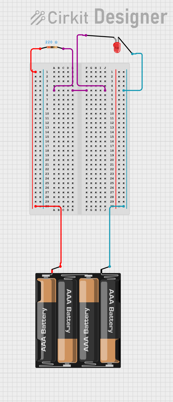
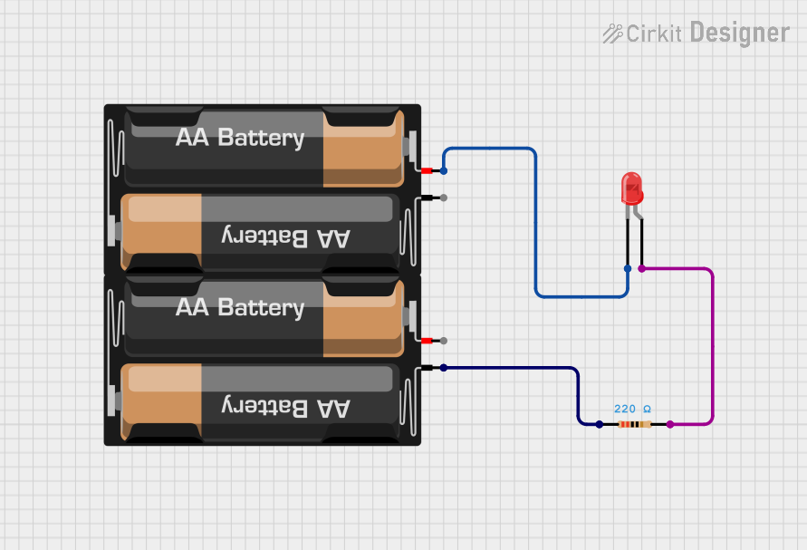
Explore Projects Built with Battery holder AAx6
Technical Specifications
General Characteristics
- Battery Compatibility: Standard AA size
- Number of Batteries: 6
- Material: Typically plastic with metal contacts
- Color: Varies (commonly black)
- Mounting: May include slots or holes for screws
Electrical Specifications
- Nominal Voltage (Series Configuration): 9V (1.5V per AA battery)
- Nominal Voltage (Parallel Configuration): 1.5V
- Maximum Current: Depends on the batteries used (refer to specific AA battery datasheet)
- Connector Type: Wires, 9V battery snap, or PCB pins
Pin Configuration and Descriptions
| Pin | Description |
|---|---|
| + | Positive terminal connected to the positive side of the battery series |
| - | Negative terminal connected to the negative side of the battery series |
Usage Instructions
Installing Batteries
- Open the battery holder, if it has a cover.
- Insert six AA batteries following the polarity markings (+/-) inside the holder.
- Ensure that the batteries are securely in place and that the contacts are clean and making good contact with the battery terminals.
Connecting to a Circuit
- Series Configuration: Connect the positive terminal of the holder to the positive input of your device and the negative terminal to the negative input. This will provide a higher voltage output (9V).
- Parallel Configuration: If a parallel configuration is needed, modifications to the holder may be required. This will provide a higher current output while maintaining a voltage of 1.5V.
Best Practices
- Always check the polarity before connecting the battery holder to your circuit.
- Do not mix old and new batteries, or batteries of different types, as this can lead to leakage or uneven discharge.
- Remove batteries if the device will not be used for an extended period to prevent battery leakage.
- Ensure that the holder is securely mounted in your project to prevent disconnections or short circuits.
Troubleshooting and FAQs
Common Issues
- Device not powering on: Check the battery orientation and ensure that the contacts are clean and making proper contact.
- Low power output: Ensure that the batteries are fresh and check for any signs of corrosion on the contacts.
- Intermittent power: Check for loose connections or damaged wires.
FAQs
Q: Can I use rechargeable AA batteries in this holder? A: Yes, as long as they are AA size, but be aware of the different voltage (typically 1.2V per rechargeable AA battery) which will affect the total output voltage.
Q: How can I mount the battery holder to my project? A: Many battery holders come with mounting holes or slots. Use screws or double-sided tape to secure the holder to your project.
Q: Is it possible to connect two holders in parallel for increased capacity? A: Yes, you can connect the positive terminals of each holder together and the negative terminals together to increase capacity, but ensure that all batteries are identical in type and charge level.
Example Code for Arduino UNO
// Example code to check the battery voltage using Arduino UNO

int batteryPin = A0; // Connect the positive terminal of the battery holder to A0

void setup() {
  Serial.begin(9600);
}

void loop() {
  int sensorValue = analogRead(batteryPin); // Read the analog value from battery
  float voltage = sensorValue * (5.0 / 1023.0); // Convert to voltage
  Serial.print("Battery Voltage: ");
  Serial.println(voltage);
  delay(1000); // Wait for a second before reading again
}
Remember to adjust the voltage conversion calculation in the code if you are using a different reference voltage or if the batteries are in a parallel configuration.