How to Use eps32_D1_mini: Examples, Pinouts, and Specs
Introduction
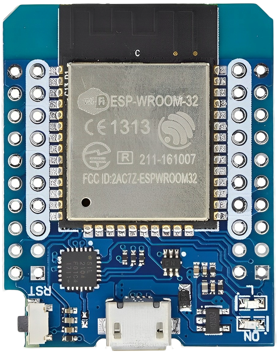
The ESP32 D1 Mini is a compact and versatile microcontroller board based on the powerful ESP32 chip. It features built-in Wi-Fi and Bluetooth capabilities, making it an excellent choice for Internet of Things (IoT) applications. Its small form factor and compatibility with various sensors and modules make it ideal for prototyping, development, and deployment in space-constrained projects.
Explore Projects Built with eps32_D1_mini


Explore Projects Built with eps32_D1_mini
Common Applications and Use Cases
- IoT devices and smart home automation
- Wireless sensor networks
- Remote monitoring and control systems
- Wearable devices
- Prototyping for Wi-Fi and Bluetooth-enabled projects
- Data logging and cloud integration
Technical Specifications
The ESP32 D1 Mini is equipped with robust hardware and connectivity features. Below are its key technical details:
Key Technical Details
- Microcontroller: ESP32 dual-core processor
- Clock Speed: Up to 240 MHz
- Flash Memory: 4 MB
- SRAM: 520 KB
- Wi-Fi: 802.11 b/g/n
- Bluetooth: v4.2 BR/EDR and BLE
- Operating Voltage: 3.3V
- Input Voltage (via USB): 5V
- GPIO Pins: 11 (multipurpose)
- Communication Protocols: UART, SPI, I2C, PWM, ADC, DAC
- Dimensions: 34.2mm x 25.6mm
Pin Configuration and Descriptions
The ESP32 D1 Mini has a total of 16 pins, each with specific functions. Below is the pinout description:
| Pin | Name | Function |
|---|---|---|
| 1 | 3V3 | 3.3V power output |
| 2 | GND | Ground |
| 3 | D0 (GPIO16) | General-purpose I/O, can be used for digital input/output |
| 4 | D1 (GPIO5) | General-purpose I/O, supports I2C SCL |
| 5 | D2 (GPIO4) | General-purpose I/O, supports I2C SDA |
| 6 | D3 (GPIO0) | General-purpose I/O, boot mode selection pin |
| 7 | D4 (GPIO2) | General-purpose I/O, onboard LED control |
| 8 | RX (GPIO3) | UART RX (serial communication receive) |
| 9 | TX (GPIO1) | UART TX (serial communication transmit) |
| 10 | A0 (GPIO36) | Analog input (ADC) |
| 11 | D5 (GPIO14) | General-purpose I/O, supports SPI SCK |
| 12 | D6 (GPIO12) | General-purpose I/O, supports SPI MISO |
| 13 | D7 (GPIO13) | General-purpose I/O, supports SPI MOSI |
| 14 | D8 (GPIO15) | General-purpose I/O, supports SPI SS |
| 15 | EN | Enable pin, used to reset the chip |
| 16 | RST | Reset pin, used to restart the microcontroller |
Usage Instructions
The ESP32 D1 Mini is easy to use and can be programmed using the Arduino IDE or other development environments. Below are the steps to get started and important considerations:
How to Use the ESP32 D1 Mini in a Circuit
Powering the Board:
- Connect the board to your computer or a USB power source using a micro-USB cable.
- Ensure the input voltage does not exceed 5V when powering via USB.
Programming the Board:
- Install the ESP32 board package in the Arduino IDE.
- Select the correct board (
ESP32 Dev Module) and port from the Tools menu. - Write or upload your code to the board.
Connecting Peripherals:
- Use the GPIO pins to connect sensors, actuators, or other modules.
- Ensure the peripherals operate at 3.3V logic levels to avoid damaging the board.
Wi-Fi and Bluetooth Setup:
- Use the built-in libraries (
WiFi.handBluetoothSerial.h) to configure wireless communication.
- Use the built-in libraries (
Example Code for Arduino IDE
The following example demonstrates how to connect the ESP32 D1 Mini to a Wi-Fi network and control the onboard LED:
#include <WiFi.h> // Include the Wi-Fi library

// Replace with your network credentials
const char* ssid = "Your_SSID";
const char* password = "Your_PASSWORD";

void setup() {
  pinMode(2, OUTPUT); // Set GPIO2 (D4) as an output pin for the onboard LED
  Serial.begin(115200); // Initialize serial communication at 115200 baud rate

  // Connect to Wi-Fi
  Serial.print("Connecting to Wi-Fi");
  WiFi.begin(ssid, password);
  while (WiFi.status() != WL_CONNECTED) {
    delay(500);
    Serial.print(".");
  }
  Serial.println("\nWi-Fi connected!");
  Serial.print("IP Address: ");
  Serial.println(WiFi.localIP()); // Print the device's IP address
}

void loop() {
  digitalWrite(2, HIGH); // Turn the LED on
  delay(1000);           // Wait for 1 second
  digitalWrite(2, LOW);  // Turn the LED off
  delay(1000);           // Wait for 1 second
}
Important Considerations and Best Practices
- Voltage Levels: Ensure all connected peripherals operate at 3.3V logic levels. Use level shifters if necessary.
- Heat Management: The ESP32 chip may heat up during operation. Ensure proper ventilation or use a heatsink if required.
- Boot Mode: Avoid pulling GPIO0 low during startup unless you intend to enter bootloader mode.
- Power Supply: Use a stable power source to avoid unexpected resets or instability.
Troubleshooting and FAQs
Common Issues and Solutions
The board is not detected by the computer:
- Ensure the correct USB driver is installed for the ESP32.
- Try using a different USB cable or port.
Wi-Fi connection fails:
- Double-check the SSID and password in your code.
- Ensure the Wi-Fi network is within range and operational.
Code upload fails:
- Verify that the correct board and port are selected in the Arduino IDE.
- Press and hold the
BOOTbutton on the board while uploading the code.
The board overheats:
- Check for excessive current draw from connected peripherals.
- Reduce the workload or add a heatsink to the ESP32 chip.
FAQs
Can I power the ESP32 D1 Mini with a battery?
Yes, you can use a 3.7V LiPo battery connected to the 3V3 pin. Ensure proper voltage regulation.Is the ESP32 D1 Mini compatible with ESP8266 shields?
No, the ESP32 D1 Mini has a different pinout and architecture compared to the ESP8266.How do I reset the board?
Press theRSTbutton to restart the microcontroller.Can I use the ESP32 D1 Mini for Bluetooth audio?
Yes, the ESP32 supports Bluetooth audio, but additional libraries and configurations are required.
This documentation provides a comprehensive guide to using the ESP32 D1 Mini effectively. For further assistance, refer to the official ESP32 documentation or community forums.