How to Use 3 Position Switch: Examples, Pinouts, and Specs
Introduction
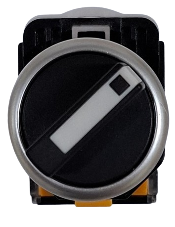
The 3 Position Switch is a versatile electromechanical component designed to connect a single input to one of three different outputs or circuits. This switch is commonly used in applications requiring multiple operational modes, such as selecting between power sources, controlling motor speeds, or toggling between different device functions. Its simple yet effective design makes it a staple in both hobbyist and industrial projects.
Explore Projects Built with 3 Position Switch

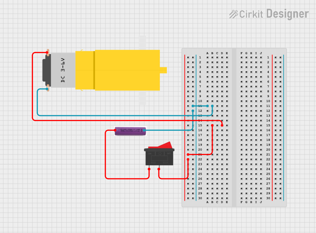
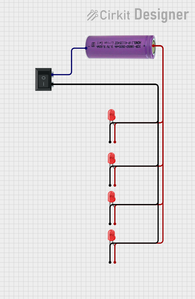

Explore Projects Built with 3 Position Switch
Common Applications
- Mode selection in electronic devices
- Motor speed control (e.g., low, medium, high)
- Power source switching (e.g., battery, solar, mains)
- Audio or video input/output selection
- Robotics and automation systems
Technical Specifications
The 3 Position Switch is available in various configurations, but the following are typical specifications for a standard model:
| Parameter | Value |
|---|---|
| Operating Voltage | 12V to 250V (varies by model) |
| Current Rating | 0.5A to 15A (varies by model) |
| Contact Resistance | ≤ 50 mΩ |
| Insulation Resistance | ≥ 100 MΩ |
| Mechanical Life | 10,000 to 50,000 cycles |
| Mounting Style | Panel mount or PCB mount |
| Switch Type | SP3T (Single Pole, Triple Throw) |
Pin Configuration and Descriptions
The 3 Position Switch typically has 4 pins or terminals. Below is a description of the pin configuration:
| Pin | Label | Description |
|---|---|---|
| 1 | Common (COM) | The input terminal that connects to one of the outputs. |
| 2 | Position 1 | Output terminal for the first position. |
| 3 | Position 2 | Output terminal for the second position. |
| 4 | Position 3 | Output terminal for the third position. |
Usage Instructions
How to Use the 3 Position Switch in a Circuit
- Identify the Pins: Locate the common (COM) pin and the three output pins (Position 1, Position 2, and Position 3) on the switch.
- Connect the Input: Attach the input signal or power source to the COM pin.
- Connect the Outputs: Connect the devices or circuits you want to control to the three output pins.
- Mount the Switch: Secure the switch to a panel or PCB as required.
- Test the Circuit: Toggle the switch to ensure proper operation in all three positions.
Important Considerations
- Voltage and Current Ratings: Ensure the switch can handle the voltage and current of your application to avoid damage or failure.
- Debouncing: When used in digital circuits, consider adding a debouncing circuit or software logic to handle switch bounce.
- Mechanical Durability: Avoid excessive force when toggling the switch to prolong its lifespan.
- Safety: If used in high-voltage applications, ensure proper insulation and spacing to prevent short circuits or electric shock.
Example: Connecting to an Arduino UNO
The 3 Position Switch can be used with an Arduino UNO to read its state and perform actions based on the selected position. Below is an example circuit and code:
Circuit
- Connect the COM pin of the switch to the 5V pin on the Arduino.
- Connect Position 1, Position 2, and Position 3 pins to Arduino digital pins 2, 3, and 4, respectively.
- Use pull-down resistors (10kΩ) on each output pin to ensure stable readings.
Code
// Define pins for the 3 Position Switch
const int pos1Pin = 2; // Pin connected to Position 1
const int pos2Pin = 3; // Pin connected to Position 2
const int pos3Pin = 4; // Pin connected to Position 3

void setup() {
  // Set switch pins as inputs
  pinMode(pos1Pin, INPUT);
  pinMode(pos2Pin, INPUT);
  pinMode(pos3Pin, INPUT);

  // Initialize serial communication for debugging
  Serial.begin(9600);
}

void loop() {
  // Read the state of each position
  bool pos1State = digitalRead(pos1Pin);
  bool pos2State = digitalRead(pos2Pin);
  bool pos3State = digitalRead(pos3Pin);

  // Determine which position is active and print to Serial Monitor
  if (pos1State) {
    Serial.println("Switch is in Position 1");
  } else if (pos2State) {
    Serial.println("Switch is in Position 2");
  } else if (pos3State) {
    Serial.println("Switch is in Position 3");
  } else {
    Serial.println("No position is active");
  }

  // Add a small delay to avoid flooding the Serial Monitor
  delay(200);
}
Troubleshooting and FAQs
Common Issues
Switch Not Working in All Positions
- Cause: Loose or incorrect wiring.
- Solution: Double-check the connections to ensure the COM pin is properly connected to the input and the output pins are connected to the correct circuits.
Intermittent Operation
- Cause: Contact wear or dirt inside the switch.
- Solution: Clean the switch contacts or replace the switch if worn out.
Incorrect Readings with Arduino
- Cause: Missing pull-down resistors or switch bounce.
- Solution: Add pull-down resistors to stabilize the signal and implement debouncing logic in the code.
FAQs
Q: Can I use the 3 Position Switch for AC applications?
A: Yes, as long as the switch's voltage and current ratings are suitable for the AC application.
Q: How do I know which pin is the COM pin?
A: The COM pin is usually labeled on the switch or can be identified using a multimeter in continuity mode.
Q: Can I use this switch to control a motor?
A: Yes, but ensure the motor's current and voltage do not exceed the switch's ratings. For high-power motors, consider using the switch to control a relay instead.
Q: What happens if I connect multiple outputs at the same time?
A: The 3 Position Switch is designed to connect only one output at a time. Connecting multiple outputs simultaneously may cause short circuits or damage the switch.