How to Use 7408: Examples, Pinouts, and Specs
Introduction
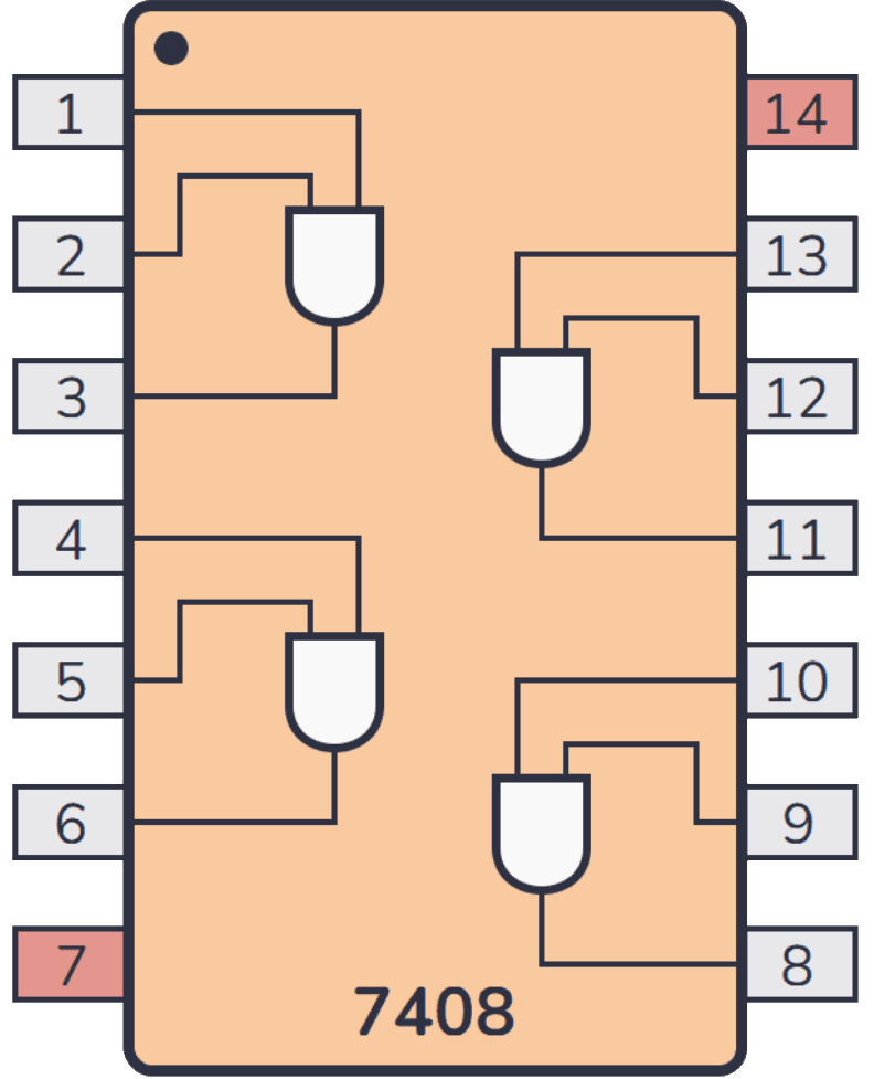
The 7408 IC is a fundamental digital component from Texas Instruments, consisting of four independent 2-input AND gates. Each gate performs the logical AND function, outputting a high level only when both its inputs are high. This IC is commonly used in digital circuits for logic operations and is a staple in both educational environments and industry applications.
Explore Projects Built with 7408

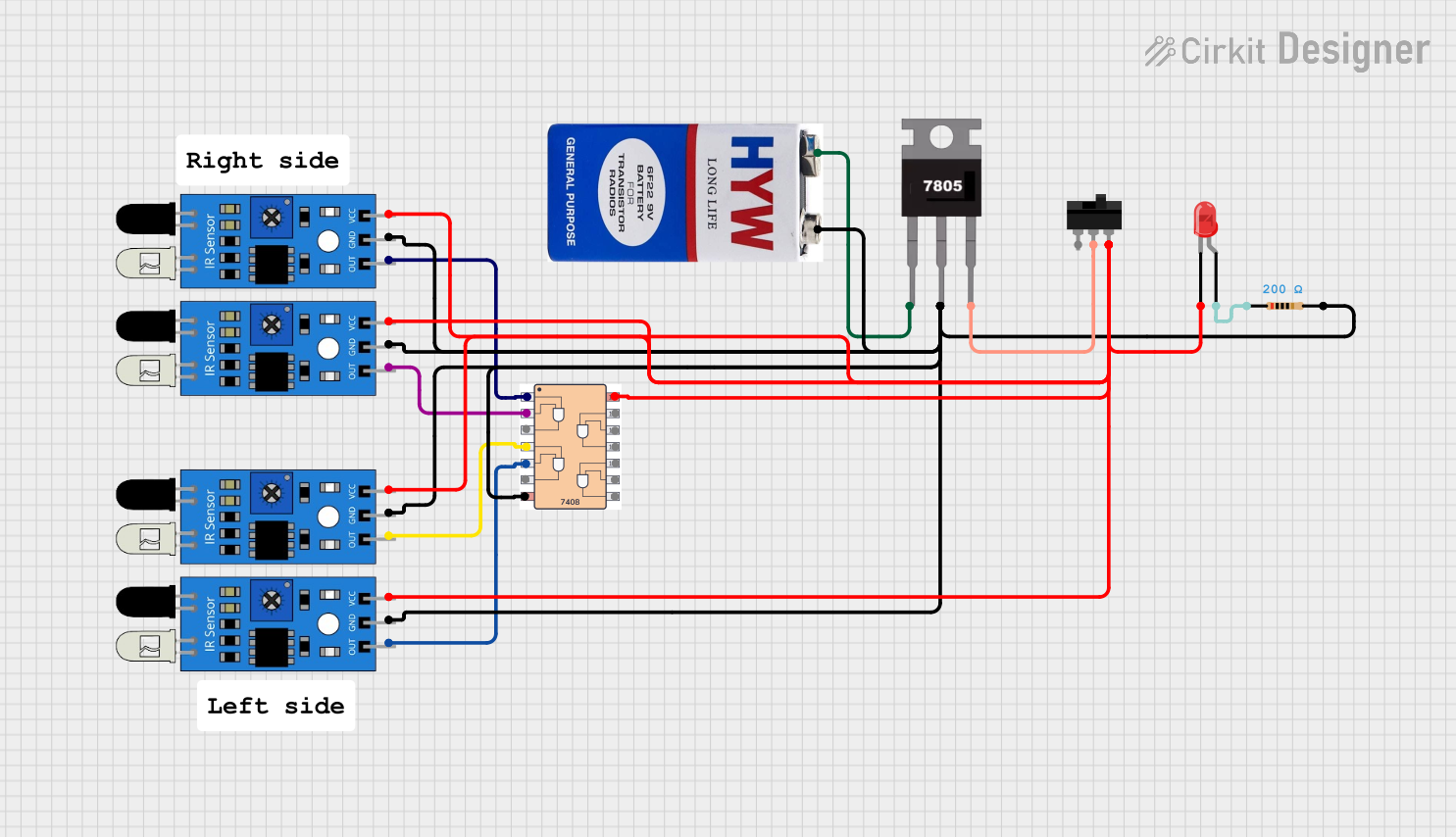
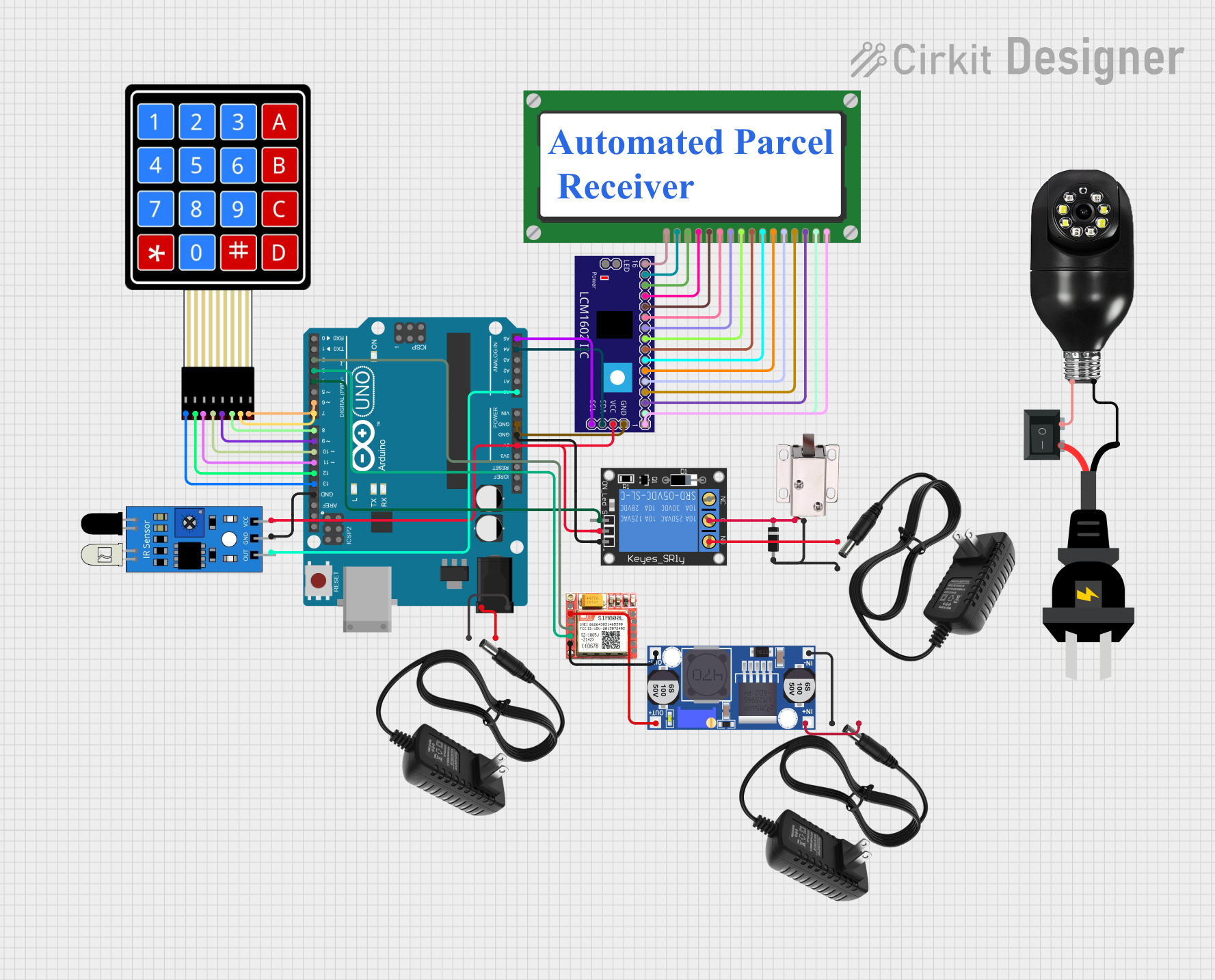

Explore Projects Built with 7408
Common Applications
- Digital logic circuits
- Signal gating
- Function generators
- Logic-based decision making circuits
- Interface switching
Technical Specifications
Key Technical Details
- Operating Voltage Range: 4.75V to 5.25V
- Standard Operating Voltage: 5V
- High-level Input Voltage (Min): 2V
- Low-level Input Voltage (Max): 0.8V
- High-level Output Current (Max): -0.8 mA
- Low-level Output Current (Max): 16 mA
- Propagation Delay Time: 15 ns (typical, at 5V)
- Operating Temperature Range: 0°C to 70°C
Pin Configuration and Descriptions
| Pin Number | Name | Description |
|---|---|---|
| 1 | 1A | Input A for Gate 1 |
| 2 | 1B | Input B for Gate 1 |
| 3 | 1Y | Output for Gate 1 |
| 4 | 2A | Input A for Gate 2 |
| 5 | 2B | Input B for Gate 2 |
| 6 | 2Y | Output for Gate 2 |
| 7 | GND | Ground (0V) |
| 8 | 3Y | Output for Gate 3 |
| 9 | 3A | Input A for Gate 3 |
| 10 | 3B | Input B for Gate 3 |
| 11 | 4Y | Output for Gate 4 |
| 12 | 4A | Input A for Gate 4 |
| 13 | 4B | Input B for Gate 4 |
| 14 | Vcc | Positive Supply Voltage (5V) |
Usage Instructions
How to Use the 7408 in a Circuit
- Power Supply Connection: Connect pin 14 (Vcc) to the positive supply voltage (5V) and pin 7 (GND) to the ground of the power supply.
- Input Connection: Apply logic signals to the input pins (1A, 1B, 2A, 2B, 3A, 3B, 4A, 4B) as required for your logic circuit.
- Output Connection: Connect the output pins (1Y, 2Y, 3Y, 4Y) to the next stage of your circuit or to an indicator like an LED with a current-limiting resistor.
Important Considerations and Best Practices
- Ensure that the power supply voltage does not exceed the recommended operating voltage range to prevent damage to the IC.
- Inputs should not be left floating; they should be connected to a high or low logic level to avoid unpredictable behavior.
- Decoupling capacitors (typically 0.1 µF) should be placed close to the IC's power pins to filter out noise and provide a stable power supply.
- Avoid exceeding the maximum current ratings for the outputs to prevent damage to the IC.
Example Circuit: Connecting 7408 to an Arduino UNO
// Define the input and output pins
const int inputPinA1 = 2; // Connect to 1A on the 7408
const int inputPinB1 = 3; // Connect to 1B on the 7408
const int outputPinY1 = 4; // Connect to 1Y on the 7408

void setup() {
  // Initialize the input and output pins
  pinMode(inputPinA1, OUTPUT);
  pinMode(inputPinB1, OUTPUT);
  pinMode(outputPinY1, INPUT);
}

void loop() {
  // Set both inputs to HIGH and check the output
  digitalWrite(inputPinA1, HIGH);
  digitalWrite(inputPinB1, HIGH);
  if (digitalRead(outputPinY1) == HIGH) {
    // The AND condition is true, perform actions here
  }

  // Add other logic combinations as needed
  // ...
}
Note: In this example, the Arduino UNO is used to simulate the inputs to the 7408. The output is read back into the Arduino for demonstration purposes. In a practical application, the output would be connected to the next stage of the digital circuit.
Troubleshooting and FAQs
Common Issues
- Output not as expected: Verify that the inputs are at correct logic levels and that the power supply is stable and within the specified range.
- IC getting hot: Check if the power supply voltage is too high or if there is a short circuit at the outputs.
Solutions and Tips
- Double-check wiring, especially the power and ground connections.
- Use a multimeter to measure the voltage levels at the inputs and outputs.
- Ensure that the total output current does not exceed the maximum specified current rating.
FAQs
Q: Can the 7408 IC be used with a 3.3V logic level system? A: The 7408 is designed for 5V systems. While it may work at 3.3V, it is not guaranteed, and the logic levels may not be compatible with other 3.3V components.
Q: What happens if I exceed the maximum output current? A: Exceeding the maximum output current can damage the IC and affect its performance and reliability.
Q: Can I replace the 7408 with another AND gate IC? A: Yes, you can replace it with another AND gate IC, but ensure that the replacement has compatible pin configurations and electrical characteristics.
This documentation provides a comprehensive guide to using the 7408 Quad 2-Input AND Gate IC. For further information, consult the manufacturer's datasheet and application notes.