
How to Use DS1302: Examples, Pinouts, and Specs
 Design with DS1302 in Cirkit Designer
Introduction
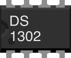
The DS1302 is a real-time clock (RTC) chip manufactured by Maxim Integrated. It is designed to keep track of the current time (hours, minutes, seconds) and date (day, month, year, and day of the week). The chip communicates with microcontrollers via a simple serial interface and features a battery backup to maintain timekeeping during power outages. Additionally, the DS1302 includes 31 bytes of static RAM for general-purpose data storage.
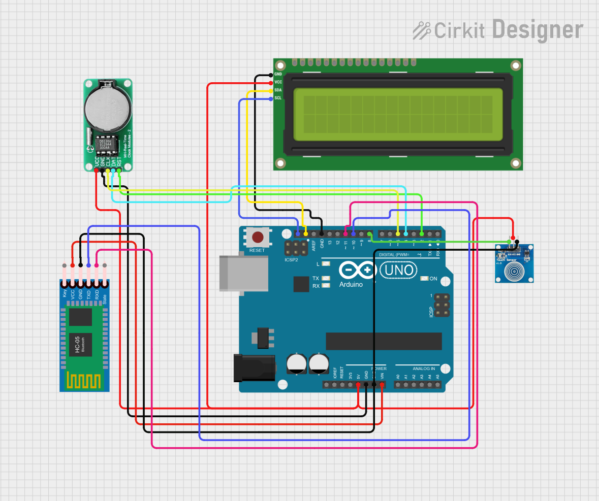
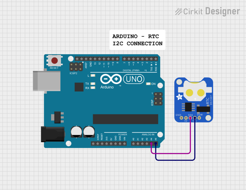
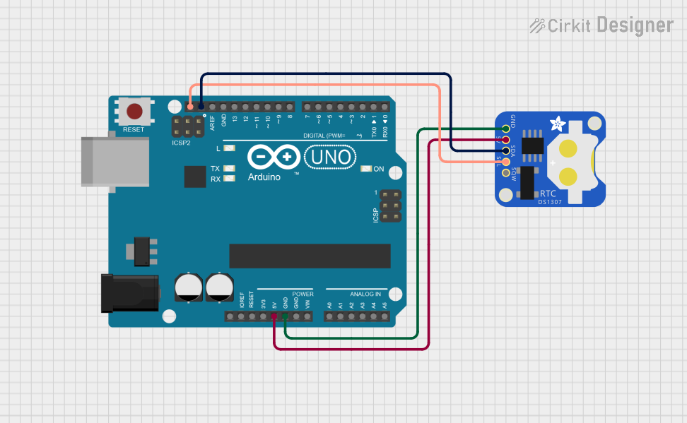
Explore Projects Built with DS1302
 Open Project in Cirkit Designer
 Open Project in Cirkit Designer
 Open Project in Cirkit Designer
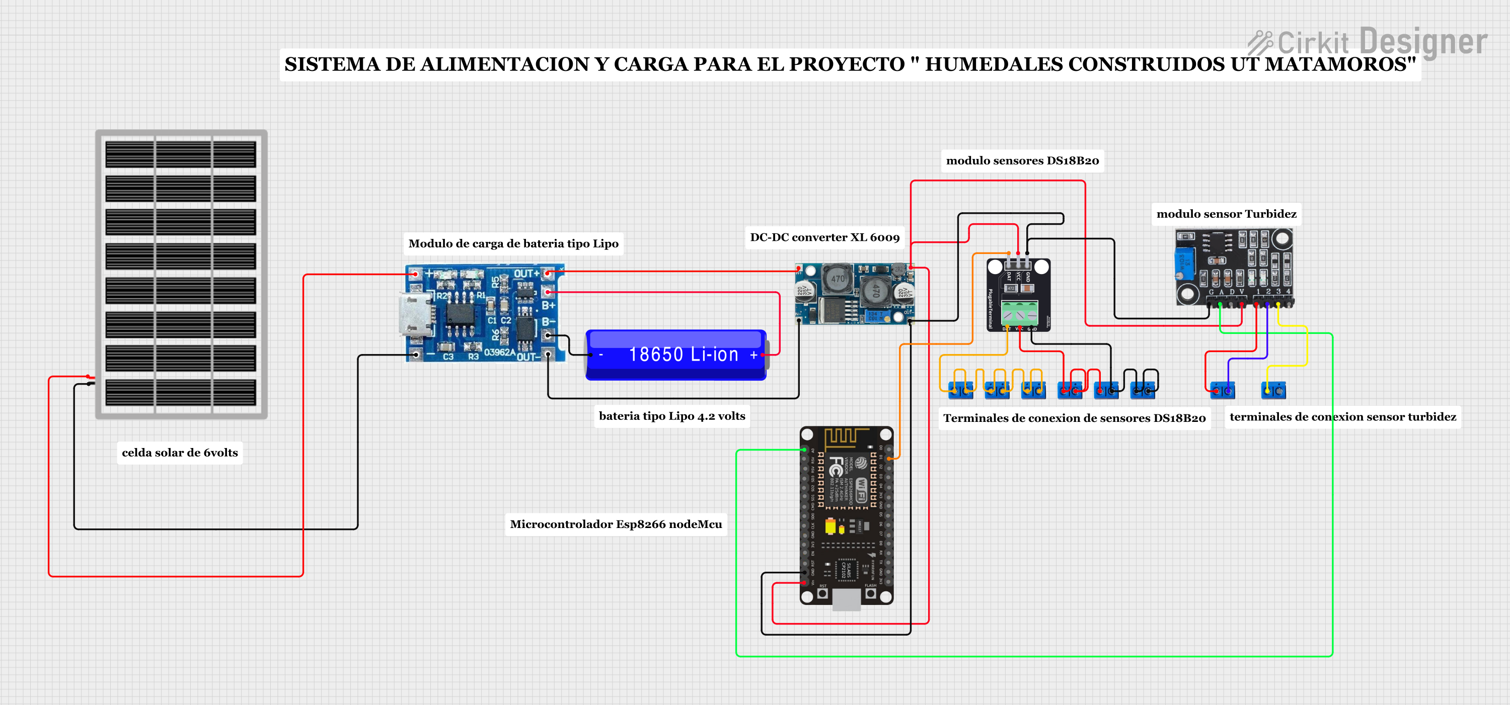 Open Project in Cirkit Designer
Explore Projects Built with DS1302
Open Project in Cirkit DesignerOpen Project in Cirkit DesignerOpen Project in Cirkit DesignerOpen Project in Cirkit DesignerCommon Applications
- Digital clocks and timers
- Data loggers
- Home automation systems
- Embedded systems requiring timekeeping
- Alarm systems and scheduling devices
Technical Specifications
The DS1302 is a low-power RTC chip with the following key specifications:
| Parameter | Value |
|---|---|
| Operating Voltage | 2.0V to 5.5V |
| Backup Battery Voltage | 2.0V to 3.5V |
| Operating Temperature | -40°C to +85°C |
| Timekeeping Accuracy | ±1 minute per month (at 25°C) |
| Communication Interface | Serial (3-wire) |
| Static RAM | 31 bytes |
| Maximum Clock Frequency | 2 MHz |
| Package Types | 8-pin DIP, SOIC |
Pin Configuration and Descriptions
The DS1302 has an 8-pin configuration. Below is the pinout and description:
| Pin | Name | Description |
|---|---|---|
| 1 | VCC1 | Primary power supply (2.0V to 5.5V). |
| 2 | X1 | Oscillator input. Connect to a 32.768 kHz crystal. |
| 3 | X2 | Oscillator output. Connect to a 32.768 kHz crystal. |
| 4 | GND | Ground. |
| 5 | RST | Reset/Enable pin. Used to initiate communication with the chip. |
| 6 | I/O | Data input/output pin for serial communication. |
| 7 | SCLK | Serial clock input. Used to synchronize data transfer. |
| 8 | VCC2 | Backup battery input (2.0V to 3.5V). Maintains timekeeping during power loss. |
Usage Instructions
How to Use the DS1302 in a Circuit
- Power Supply: Connect the primary power supply to
VCC1and ground toGND. For backup power, connect a 3V coin cell battery toVCC2. - Crystal Oscillator: Attach a 32.768 kHz crystal between the
X1andX2pins. No external capacitors are required. - Microcontroller Interface: Connect the
RST,I/O, andSCLKpins to the corresponding GPIO pins on your microcontroller. - Pull-Up Resistor: Use a pull-up resistor (typically 10kΩ) on the
I/Oline to ensure proper communication.
Important Considerations
- Ensure the crystal oscillator is of high quality to maintain accurate timekeeping.
- Avoid excessive noise on the power supply lines, as it may affect the RTC's performance.
- Use a decoupling capacitor (e.g., 0.1 µF) near the
VCC1pin to stabilize the power supply.
Example: Connecting DS1302 to Arduino UNO
Below is an example of how to interface the DS1302 with an Arduino UNO and set the time.
Circuit Connections
| DS1302 Pin | Arduino UNO Pin |
|---|---|
| RST | Digital Pin 7 |
| I/O | Digital Pin 6 |
| SCLK | Digital Pin 5 |
| VCC1 | 5V |
| GND | GND |
Arduino Code Example
#include <DS1302.h>

// Define DS1302 pins
const int RST_PIN = 7;  // Reset pin
const int IO_PIN = 6;   // Data I/O pin
const int SCLK_PIN = 5; // Serial clock pin

// Create DS1302 object
DS1302 rtc(RST_PIN, IO_PIN, SCLK_PIN);

void setup() {
  Serial.begin(9600);

  // Set the time (Year, Month, Day, Hour, Minute, Second)
  rtc.setTime(2023, 10, 15, 14, 30, 0); // Example: 15th Oct 2023, 14:30:00

  Serial.println("DS1302 RTC Initialized");
}

void loop() {
  // Get the current time
  Time t = rtc.getTime();

  // Print the time to the Serial Monitor
  Serial.print("Time: ");
  Serial.print(t.hour);
  Serial.print(":");
  Serial.print(t.min);
  Serial.print(":");
  Serial.println(t.sec);

  // Print the date
  Serial.print("Date: ");
  Serial.print(t.date);
  Serial.print("/");
  Serial.print(t.mon);
  Serial.print("/");
  Serial.println(t.year);

  delay(1000); // Update every second
}
Troubleshooting and FAQs
Common Issues
RTC Not Keeping Time
- Ensure the backup battery is properly connected to
VCC2. - Verify the crystal oscillator is functioning correctly and is of the correct frequency (32.768 kHz).
- Ensure the backup battery is properly connected to
Communication Failure
- Check the connections between the DS1302 and the microcontroller.
- Ensure the
RST,I/O, andSCLKpins are correctly assigned in the code.
Incorrect Time or Date
- Verify that the time and date are set correctly in the code.
- Ensure the microcontroller's clock speed matches the expected frequency.
FAQs
Q: Can the DS1302 operate without a backup battery?
A: Yes, but it will lose the time and date information if the primary power supply is disconnected.
Q: What is the purpose of the 31 bytes of RAM?
A: The RAM can be used to store user-defined data that needs to be retained during power outages.
Q: Can I use a different crystal oscillator frequency?
A: No, the DS1302 is designed to work specifically with a 32.768 kHz crystal for accurate timekeeping.
Q: How long does the backup battery last?
A: The backup battery can last several years, depending on its capacity and the DS1302's low power consumption.
By following this documentation, you can effectively integrate the DS1302 RTC into your projects for reliable timekeeping functionality.