Cirkit Designer Logo
Cirkit Designer
Your all-in-one circuit design IDE
Home / 
Component Documentation

How to Use Adafruit 16-Channel 12-bit PWM Servo Driver - I2C: Examples, Pinouts, and Specs

Image of Adafruit 16-Channel 12-bit PWM Servo Driver - I2C
Cirkit Designer LogoDesign with Adafruit 16-Channel 12-bit PWM Servo Driver - I2C in Cirkit Designer

Introduction

The Adafruit 16-Channel 12-bit PWM Servo Driver is an essential tool for hobbyists and engineers alike, enabling the control of up to 16 servos with precision and ease. Utilizing the I2C communication protocol, this driver board minimizes pin usage on a microcontroller, such as an Arduino UNO, by requiring only two pins for control. It is ideal for robotics, automation projects, and any application where multiple PWM outputs are needed, such as LED lighting control.

Explore Projects Built with Adafruit 16-Channel 12-bit PWM Servo Driver - I2C

Use Cirkit Designer to design, explore, and prototype these projects online. Some projects support real-time simulation. Click "Open Project" to start designing instantly!
Arduino-Controlled Multi-Servo Positioning System with Potentiometer Feedback
Image of robootic arm: A project utilizing Adafruit 16-Channel 12-bit PWM Servo Driver - I2C in a practical application
This circuit uses an Arduino UNO to control five servos through an Adafruit 16-Channel 12-bit PWM Servo Driver, with the position of each servo being adjusted by a corresponding potentiometer. The Arduino reads the analog values from the potentiometers connected to its analog inputs and sends PWM signals to the servos via the I2C-connected PWM driver. The servos are powered by a separate power supply that also powers the PWM driver, ensuring adequate current for servo operation.
Cirkit Designer LogoOpen Project in Cirkit Designer
Arduino-Controlled Servo Driver for Multi-Channel PWM Applications
Image of SPG: A project utilizing Adafruit 16-Channel 12-bit PWM Servo Driver - I2C in a practical application
This circuit is designed to control multiple servo motors using an Arduino Mega 2560 microcontroller and an Adafruit 16-Channel 12-bit PWM Servo Driver. The Arduino communicates with the PWM driver over I2C (using SDA and SCL lines) to send PWM signals to individual servos for precise angle control. A separate 5V power supply provides power to the PWM driver and the servos, ensuring stable operation for high-current applications.
Cirkit Designer LogoOpen Project in Cirkit Designer
Arduino UNO and Bluetooth-Controlled Servo Motor System with PWM Driver
Image of Robotic Arm I: A project utilizing Adafruit 16-Channel 12-bit PWM Servo Driver - I2C in a practical application
This circuit uses an Arduino UNO to control multiple servos via an Adafruit 16-Channel 12-bit PWM Servo Driver, with communication facilitated by an HC-05 Bluetooth module. The Arduino communicates with the PWM driver over I2C, and the servos are powered and controlled through the PWM driver, allowing for precise servo movements based on commands received over Bluetooth.
Cirkit Designer LogoOpen Project in Cirkit Designer
Arduino UNO Controlled Battery-Powered Servo Motor System
Image of pwm servo: A project utilizing Adafruit 16-Channel 12-bit PWM Servo Driver - I2C in a practical application
This circuit uses an Arduino UNO to control a 16-Channel PWM Servo Driver, which in turn drives a servo motor. The Arduino communicates with the PWM driver via I2C and is powered by a 3xAA battery pack, enabling precise control of the servo motor's position.
Cirkit Designer LogoOpen Project in Cirkit Designer

Explore Projects Built with Adafruit 16-Channel 12-bit PWM Servo Driver - I2C

Use Cirkit Designer to design, explore, and prototype these projects online. Some projects support real-time simulation. Click "Open Project" to start designing instantly!
Image of robootic arm: A project utilizing Adafruit 16-Channel 12-bit PWM Servo Driver - I2C in a practical application
Arduino-Controlled Multi-Servo Positioning System with Potentiometer Feedback
This circuit uses an Arduino UNO to control five servos through an Adafruit 16-Channel 12-bit PWM Servo Driver, with the position of each servo being adjusted by a corresponding potentiometer. The Arduino reads the analog values from the potentiometers connected to its analog inputs and sends PWM signals to the servos via the I2C-connected PWM driver. The servos are powered by a separate power supply that also powers the PWM driver, ensuring adequate current for servo operation.
Cirkit Designer LogoOpen Project in Cirkit Designer
Image of SPG: A project utilizing Adafruit 16-Channel 12-bit PWM Servo Driver - I2C in a practical application
Arduino-Controlled Servo Driver for Multi-Channel PWM Applications
This circuit is designed to control multiple servo motors using an Arduino Mega 2560 microcontroller and an Adafruit 16-Channel 12-bit PWM Servo Driver. The Arduino communicates with the PWM driver over I2C (using SDA and SCL lines) to send PWM signals to individual servos for precise angle control. A separate 5V power supply provides power to the PWM driver and the servos, ensuring stable operation for high-current applications.
Cirkit Designer LogoOpen Project in Cirkit Designer
Image of Robotic Arm I: A project utilizing Adafruit 16-Channel 12-bit PWM Servo Driver - I2C in a practical application
Arduino UNO and Bluetooth-Controlled Servo Motor System with PWM Driver
This circuit uses an Arduino UNO to control multiple servos via an Adafruit 16-Channel 12-bit PWM Servo Driver, with communication facilitated by an HC-05 Bluetooth module. The Arduino communicates with the PWM driver over I2C, and the servos are powered and controlled through the PWM driver, allowing for precise servo movements based on commands received over Bluetooth.
Cirkit Designer LogoOpen Project in Cirkit Designer
Image of pwm servo: A project utilizing Adafruit 16-Channel 12-bit PWM Servo Driver - I2C in a practical application
Arduino UNO Controlled Battery-Powered Servo Motor System
This circuit uses an Arduino UNO to control a 16-Channel PWM Servo Driver, which in turn drives a servo motor. The Arduino communicates with the PWM driver via I2C and is powered by a 3xAA battery pack, enabling precise control of the servo motor's position.
Cirkit Designer LogoOpen Project in Cirkit Designer

Technical Specifications

Key Features

  • Channels: 16 PWM outputs
  • Resolution: 12-bit (4096 steps)
  • Frequency: 40Hz to 1000Hz PWM
  • Voltage: 5V to 6V for V+ (Servo Power Supply)
  • Logic Voltage: 3.3V or 5V compatible
  • Interface: I2C
  • Dimensions: 62.5mm x 25.4mm x 3mm / 2.5" x 1.0" x 0.1"

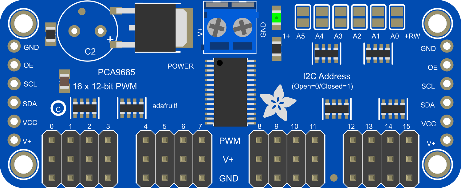
Pin Configuration and Descriptions

Pin Number Name Description
1 GND Ground connection
2 VCC Logic power supply (3.3V to 5V)
3 SDA I2C Data Line
4 SCL I2C Clock Line
5-20 PWM0 to PWM15 PWM output to servos
21 OE Output enable (active low)
22 OUTDRV Output driver mode (totem pole/ open-drain)
23 V+ Servo power supply (5V to 6V)

Usage Instructions

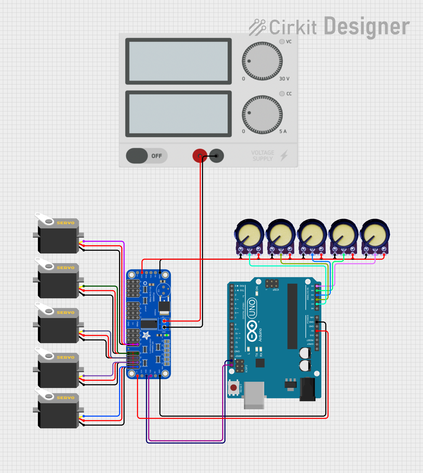
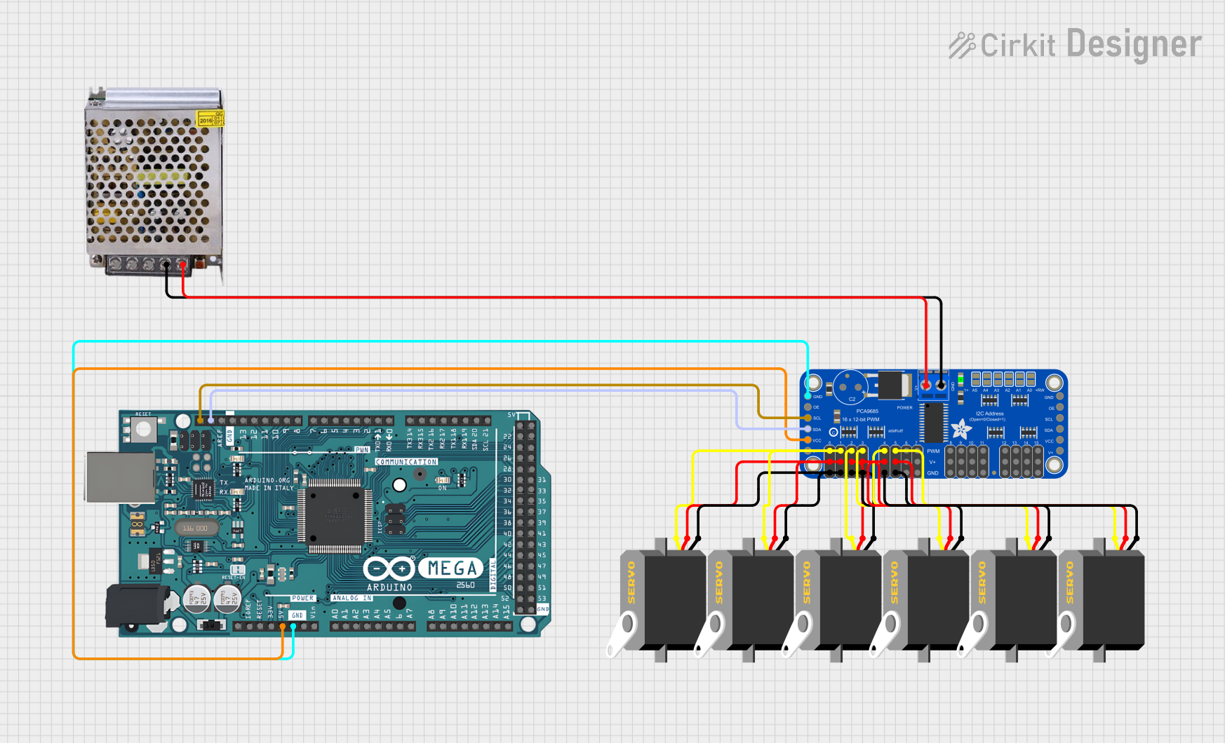
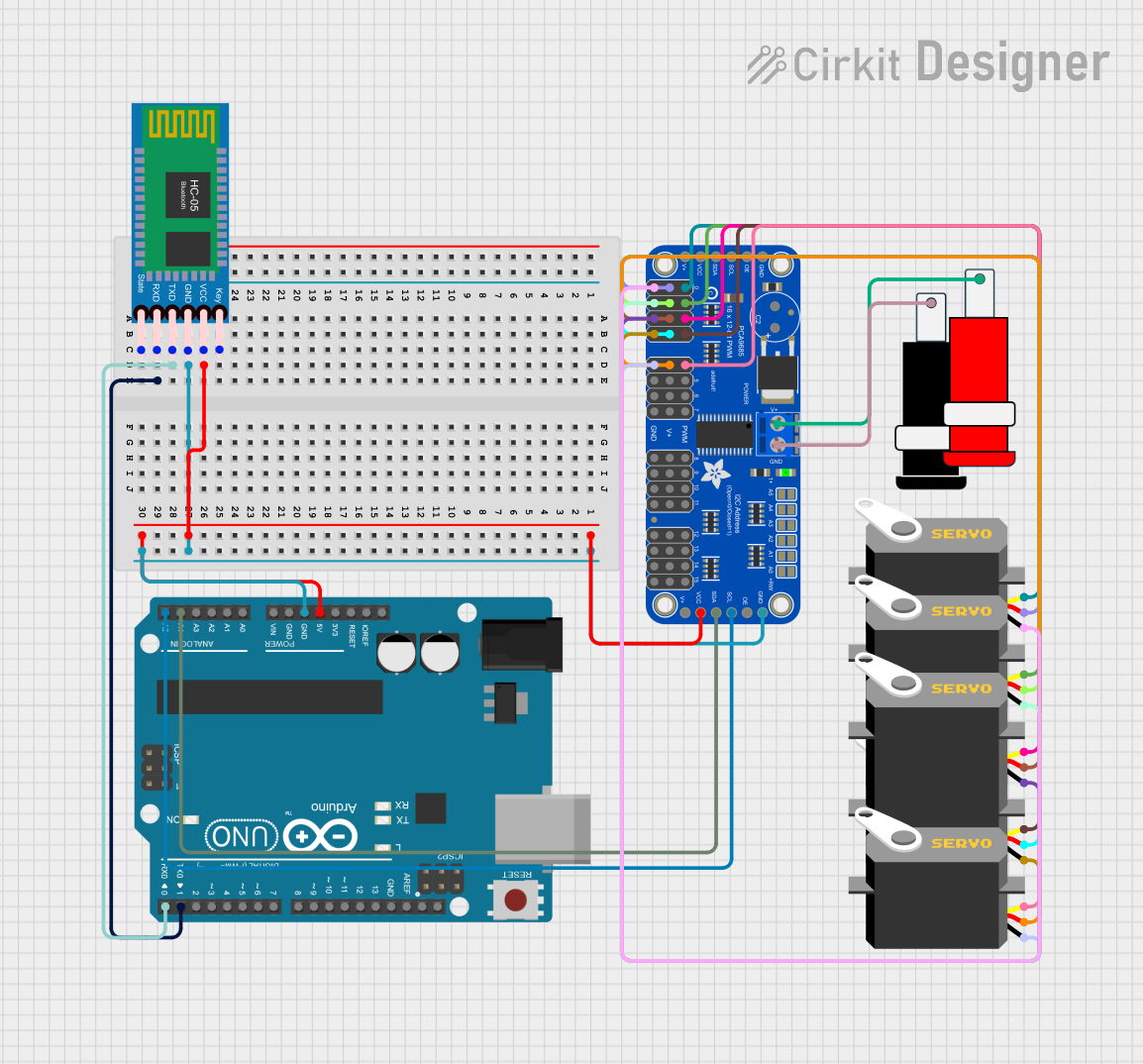
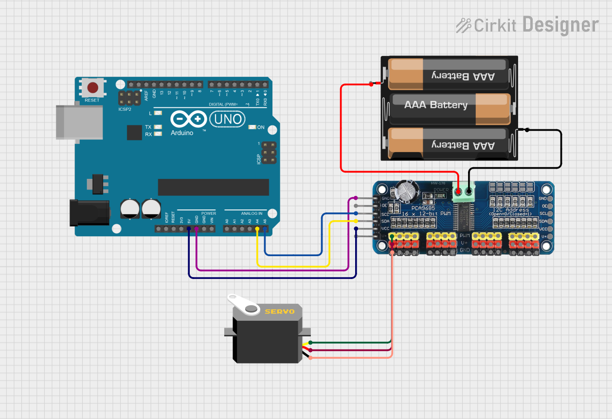
Connecting to an Arduino UNO

  1. Connect GND on the driver to the Arduino's ground.
  2. Connect VCC to the Arduino's 5V pin.
  3. Connect SDA to the Arduino's A4 (SDA) pin.
  4. Connect SCL to the Arduino's A5 (SCL) pin.
  5. Connect V+ to an external 5V to 6V power supply.
  6. Connect your servos to the PWM outputs (PWM0 to PWM15).

Library Installation

Before using the driver with an Arduino, install the Adafruit PWM Servo Driver library via the Library Manager in the Arduino IDE.

Example Code

#include <Wire.h>
#include <Adafruit_PWMServoDriver.h>

// Initialize the PWM driver
Adafruit_PWMServoDriver pwm = Adafruit_PWMServoDriver();

void setup() {
  pwm.begin();
  pwm.setPWMFreq(60);  // Set the frequency to 60 Hz
}

void loop() {
  // Example: Turn servo on channel 0 to the middle position
  pwm.setPWM(0, 0, 2048);
  delay(1000);
  
  // Turn servo on channel 0 to the minimum position
  pwm.setPWM(0, 0, 409);
  delay(1000);
  
  // Turn servo on channel 0 to the maximum position
  pwm.setPWM(0, 0, 3687);
  delay(1000);
}

Important Considerations and Best Practices

  • Ensure that the external power supply for V+ is capable of providing sufficient current for all connected servos.
  • Do not exceed the recommended voltage range for V+.
  • Use a separate power supply for the servos to prevent noise and voltage drops on the logic side.
  • Always use common ground for the Arduino, driver board, and external power supply.

Troubleshooting and FAQs

Common Issues

  • Servos not responding: Check connections, ensure that the I2C address is correct, and that the external power supply is properly connected and turned on.
  • Inaccurate servo movement: Verify that the PWM frequency and pulse widths are set correctly for your specific servos.
  • Noise or erratic behavior: Ensure that the power supply is adequate and that there is a common ground.

FAQs

Q: Can I chain multiple boards together? A: Yes, you can chain up to 62 boards for a total of 992 PWM outputs. Set unique I2C addresses for each board using the address jumpers.

Q: What is the maximum number of servos I can control with one board? A: You can control up to 16 servos per board.

Q: Do I need to use an external power supply for the servos? A: Yes, an external power supply is necessary to provide sufficient current for the servos without affecting the microcontroller's operation.

Q: Can I use this board with a Raspberry Pi or other microcontrollers? A: Absolutely, as long as the device supports I2C communication, you can use this board with it.

For further assistance, consult the Adafruit support forums or the product's official documentation.