How to Use DG01D-E: Examples, Pinouts, and Specs
Introduction
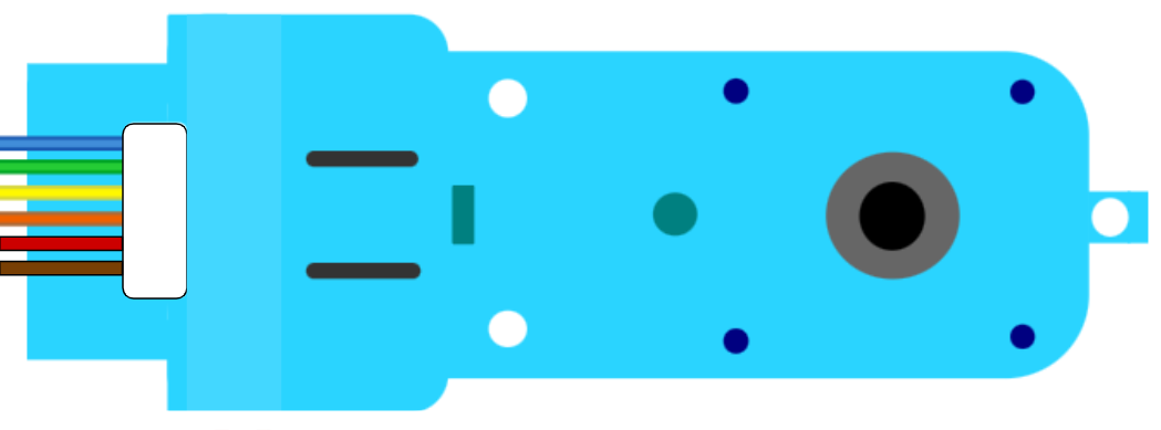
The DG01D-E is a rotary encoder manufactured by Sparkfun, designed to detect the position and rotation of a shaft. It converts mechanical position into an electrical signal, enabling precise control in various applications. Rotary encoders like the DG01D-E are commonly used in robotics, industrial controls, and user interface devices such as volume knobs and jog wheels.
Explore Projects Built with DG01D-E
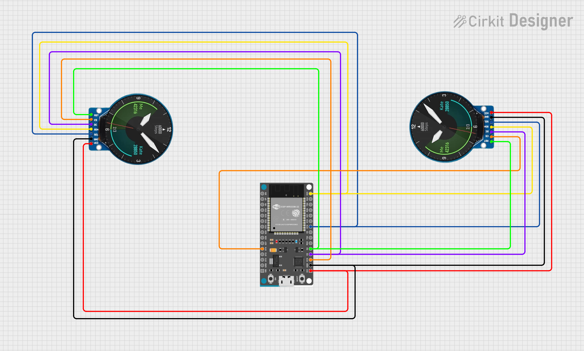


Explore Projects Built with DG01D-E
Technical Specifications
Key Technical Details
| Parameter | Value |
|---|---|
| Manufacturer | Sparkfun |
| Part ID | DG01D-E |
| Operating Voltage | 5V DC |
| Current Consumption | 10mA (typical) |
| Output Type | Quadrature (A and B channels) |
| Resolution | 20 pulses per revolution |
| Shaft Diameter | 6mm |
| Operating Temperature | -10°C to 70°C |
Pin Configuration and Descriptions
| Pin Number | Pin Name | Description |
|---|---|---|
| 1 | GND | Ground |
| 2 | VCC | Power Supply (5V DC) |
| 3 | A | Channel A output (quadrature signal) |
| 4 | B | Channel B output (quadrature signal) |
| 5 | SW | Switch output (active low when pressed) |
Usage Instructions
How to Use the DG01D-E in a Circuit
- Power Supply: Connect the VCC pin to a 5V DC power supply and the GND pin to the ground.
- Signal Outputs: Connect the A and B pins to the input pins of a microcontroller or an interface circuit to read the quadrature signals.
- Switch Output: Connect the SW pin to a digital input pin of a microcontroller to detect the switch press.
Important Considerations and Best Practices
- Debouncing: The mechanical switch may produce noise or "bouncing" when pressed. Implement software debouncing to ensure reliable switch detection.
- Pull-up Resistors: Use internal or external pull-up resistors for the switch output to ensure a defined logic level when the switch is not pressed.
- Signal Filtering: If the encoder is used in a noisy environment, consider adding capacitors to filter out high-frequency noise on the signal lines.
Example Circuit Diagram
Below is a simple example of how to connect the DG01D-E to an Arduino UNO:
DG01D-E Pin | Arduino UNO Pin
------------|----------------
GND         | GND
VCC         | 5V
A           | Digital Pin 2
B           | Digital Pin 3
SW          | Digital Pin 4
Example Arduino Code
// DG01D-E Rotary Encoder Example Code
// Connect the encoder pins as follows:
// GND -> GND
// VCC -> 5V
// A -> Digital Pin 2
// B -> Digital Pin 3
// SW -> Digital Pin 4

#define ENCODER_PIN_A 2
#define ENCODER_PIN_B 3
#define SWITCH_PIN 4

volatile int encoderValue = 0;
volatile bool switchPressed = false;

void setup() {
  pinMode(ENCODER_PIN_A, INPUT);
  pinMode(ENCODER_PIN_B, INPUT);
  pinMode(SWITCH_PIN, INPUT_PULLUP);

  attachInterrupt(digitalPinToInterrupt(ENCODER_PIN_A),
                  encoderISR, CHANGE);
  attachInterrupt(digitalPinToInterrupt(SWITCH_PIN),
                  switchISR, FALLING);

  Serial.begin(9600);
}

void loop() {
  static int lastEncoderValue = 0;
  static bool lastSwitchState = false;

  if (encoderValue != lastEncoderValue) {
    Serial.print("Encoder Value: ");
    Serial.println(encoderValue);
    lastEncoderValue = encoderValue;
  }

  if (switchPressed != lastSwitchState) {
    Serial.print("Switch Pressed: ");
    Serial.println(switchPressed);
    lastSwitchState = switchPressed;
  }
}

void encoderISR() {
  int stateA = digitalRead(ENCODER_PIN_A);
  int stateB = digitalRead(ENCODER_PIN_B);

  if (stateA == stateB) {
    encoderValue++;
  } else {
    encoderValue--;
  }
}

void switchISR() {
  switchPressed = !switchPressed;
}
Troubleshooting and FAQs
Common Issues
- No Signal Output: Ensure that the power supply connections (VCC and GND) are correct and that the encoder is receiving 5V DC.
- Erratic Readings: Check for proper debouncing of the switch and ensure that the signal lines are not picking up noise.
- Switch Not Detected: Verify that the switch pin is configured with a pull-up resistor and that the interrupt is correctly set up.
Solutions and Tips for Troubleshooting
- Check Connections: Double-check all wiring connections to ensure they are secure and correct.
- Use Pull-up Resistors: Ensure that the switch pin has a pull-up resistor to maintain a defined logic level.
- Implement Debouncing: Use software debouncing techniques to filter out noise from the mechanical switch.
FAQs
Q: Can the DG01D-E be used with a 3.3V microcontroller? A: The DG01D-E is designed for 5V operation. Using it with a 3.3V microcontroller may result in unreliable performance. Consider using a level shifter if necessary.
Q: How do I increase the resolution of the encoder? A: The resolution of the DG01D-E is fixed at 20 pulses per revolution. To increase resolution, you may need to use a different encoder with a higher resolution.
Q: What is the maximum rotation speed the encoder can handle? A: The maximum rotation speed depends on the ability of your microcontroller to read and process the signals. Ensure that your code and hardware can handle the expected speed.
By following this documentation, users can effectively integrate the DG01D-E rotary encoder into their projects, ensuring precise control and reliable performance.