How to Use CAMERA: Examples, Pinouts, and Specs
Introduction
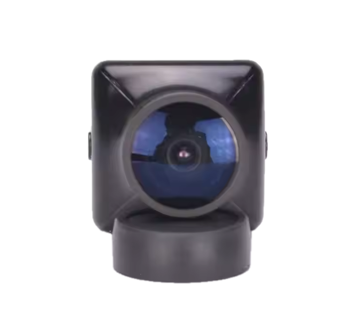
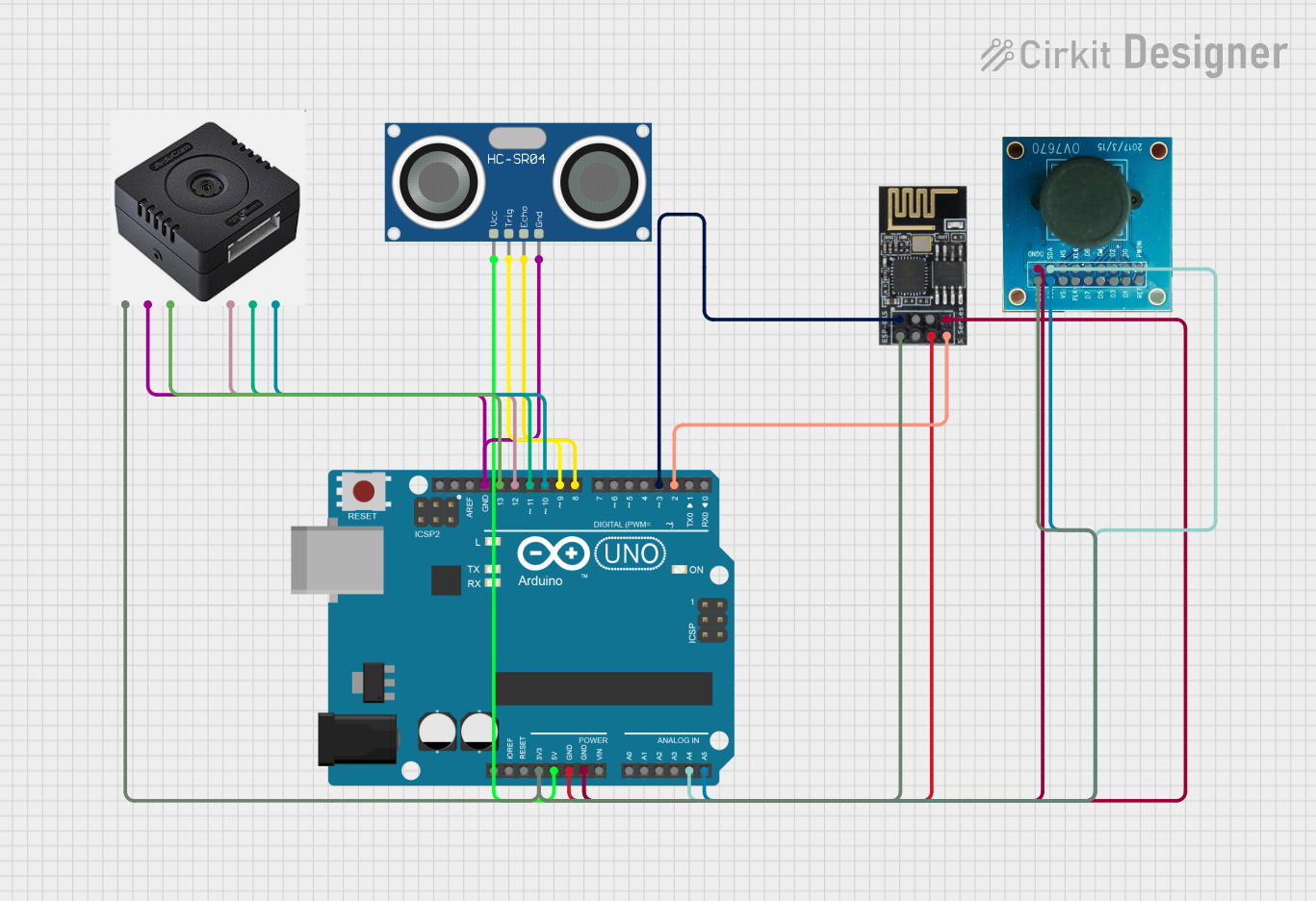
A camera module is an electronic device used to capture images or video. It is commonly used in various applications such as surveillance, photography, and video recording. Camera modules can be integrated into a wide range of devices, including smartphones, security systems, and embedded systems like the Arduino UNO.
Explore Projects Built with CAMERA
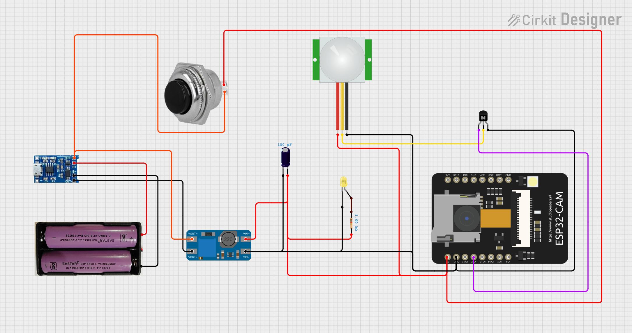
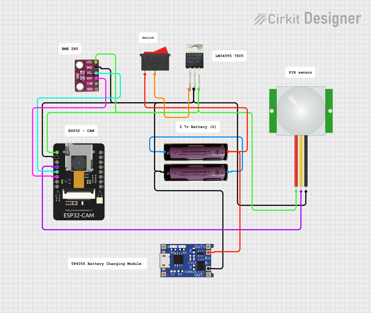
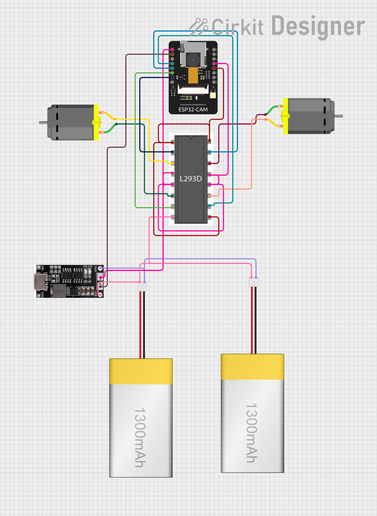
Explore Projects Built with CAMERA
Technical Specifications
Key Technical Details
| Specification | Value |
|---|---|
| Resolution | 640x480 (VGA) to 1920x1080 (Full HD) |
| Interface | I2C, SPI, UART |
| Operating Voltage | 3.3V - 5V |
| Power Consumption | 150mW - 300mW |
| Frame Rate | 30fps - 60fps |
| Lens Type | Fixed focus, Auto focus |
| Field of View | 60° - 120° |
| Operating Temperature | -20°C to 70°C |
Pin Configuration and Descriptions
| Pin Number | Pin Name | Description |
|---|---|---|
| 1 | VCC | Power supply (3.3V - 5V) |
| 2 | GND | Ground |
| 3 | SDA | I2C Data Line |
| 4 | SCL | I2C Clock Line |
| 5 | TX | UART Transmit |
| 6 | RX | UART Receive |
| 7 | MISO | SPI Master In Slave Out |
| 8 | MOSI | SPI Master Out Slave In |
| 9 | SCK | SPI Clock |
| 10 | CS | Chip Select for SPI |
Usage Instructions
How to Use the Camera Module in a Circuit
- Power Supply: Connect the VCC pin to a 3.3V or 5V power supply and the GND pin to the ground.
- Communication Interface: Choose the appropriate communication interface (I2C, SPI, or UART) based on your application.
- For I2C: Connect SDA to the data line and SCL to the clock line.
- For SPI: Connect MISO, MOSI, SCK, and CS to the respective pins on your microcontroller.
- For UART: Connect TX to the microcontroller's RX pin and RX to the microcontroller's TX pin.
- Initialization: Initialize the camera module in your code by setting up the communication interface and configuring the camera settings (resolution, frame rate, etc.).
Important Considerations and Best Practices
- Power Supply: Ensure that the power supply voltage matches the camera module's requirements to avoid damage.
- Noise Reduction: Use decoupling capacitors near the power pins to reduce noise and ensure stable operation.
- Lens Cleaning: Keep the lens clean to maintain image quality. Use a soft, lint-free cloth for cleaning.
- Heat Management: Ensure proper ventilation to prevent overheating, especially in high-power applications.
Example Code for Arduino UNO
#include <Wire.h>
#include <ArduCAM.h>
#include <SPI.h>
#include <SD.h>

// Define the camera module's CS pin
#define CS_PIN 10

ArduCAM myCAM(OV2640, CS_PIN);

void setup() {
  // Initialize Serial communication
  Serial.begin(115200);
  // Initialize SPI communication
  SPI.begin();
  // Initialize the camera module
  myCAM.init();

  // Check if the camera module is detected
  if (myCAM.checkCameraModule()) {
    Serial.println("Camera module detected.");
  } else {
    Serial.println("Camera module not detected.");
    while (1);
  }

  // Set the camera resolution
  myCAM.setResolution(OV2640_320x240);

  // Initialize the SD card
  if (!SD.begin(CS_PIN)) {
    Serial.println("SD card initialization failed.");
    while (1);
  }
}

void loop() {
  // Capture an image
  myCAM.captureImage();

  // Save the image to the SD card
  File imageFile = SD.open("image.jpg", FILE_WRITE);
  if (imageFile) {
    myCAM.saveImage(imageFile);
    imageFile.close();
    Serial.println("Image saved to SD card.");
  } else {
    Serial.println("Failed to open file for writing.");
  }

  // Add a delay before capturing the next image
  delay(5000);
}
Troubleshooting and FAQs
Common Issues and Solutions
Camera Module Not Detected
- Solution: Check the wiring connections and ensure that the power supply voltage is correct. Verify that the communication interface is properly initialized in the code.
Poor Image Quality
- Solution: Clean the lens and ensure that it is free from dust and smudges. Adjust the camera settings (resolution, focus) in the code.
SD Card Initialization Failed
- Solution: Ensure that the SD card is properly inserted and formatted. Check the CS pin connection and verify that the SD card library is included in the code.
FAQs
Can I use the camera module with a 3.3V power supply?
- Yes, the camera module can operate with a 3.3V or 5V power supply. Ensure that the voltage matches the module's requirements.
How do I change the camera resolution?
- You can change the camera resolution by calling the
setResolution()function in your code and passing the desired resolution as a parameter.
- You can change the camera resolution by calling the
What is the maximum frame rate of the camera module?
- The maximum frame rate of the camera module is typically 60fps, but it may vary depending on the resolution and other settings.
By following this documentation, you should be able to successfully integrate and use the camera module in your projects. If you encounter any issues, refer to the troubleshooting section or consult the FAQs for additional guidance.