How to Use Flow sensor YF-B7: Examples, Pinouts, and Specs
Introduction
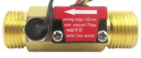
The YF-B7 is a water flow sensor manufactured by Seeed Studio, with the part ID Y7-B7. It is designed to measure the flow rate of liquids using a turbine mechanism. As liquid flows through the sensor, it spins an internal rotor, which generates a series of electrical pulses. These pulses can be read by a microcontroller to calculate the flow rate in liters per minute (L/min).
This sensor is widely used in applications such as water dispensers, irrigation systems, liquid flow monitoring, and industrial fluid control systems. Its compact design and reliable performance make it suitable for both hobbyist and professional projects.
Explore Projects Built with Flow sensor YF-B7
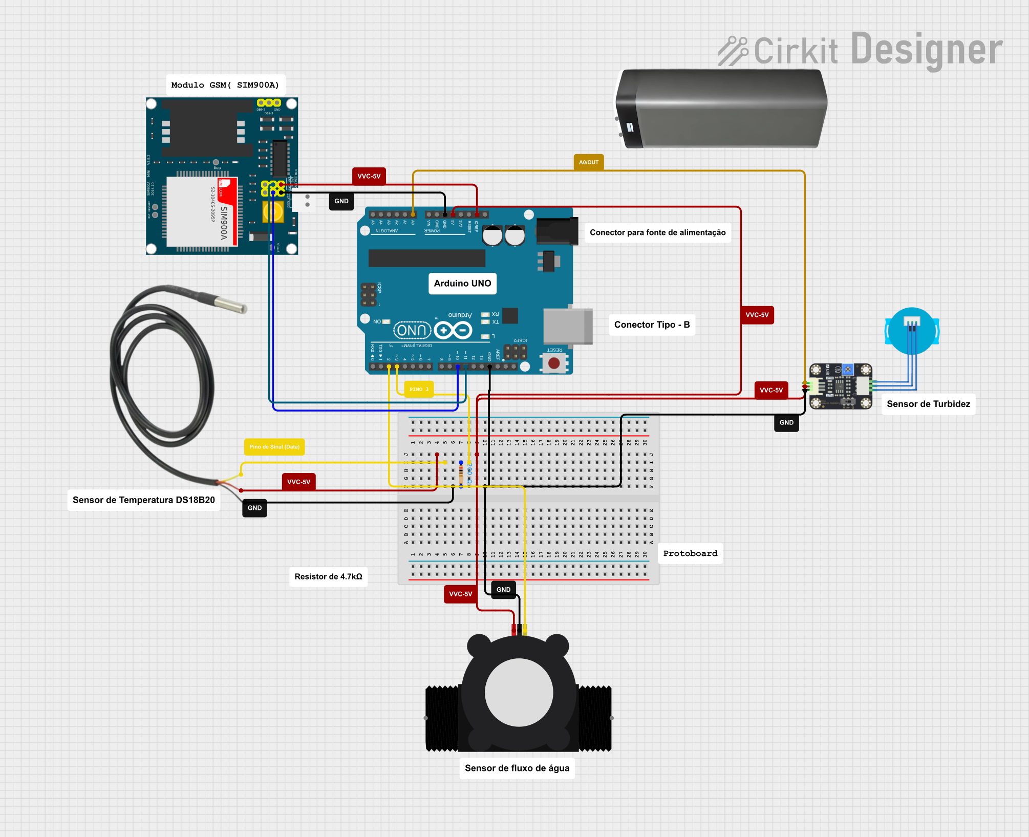
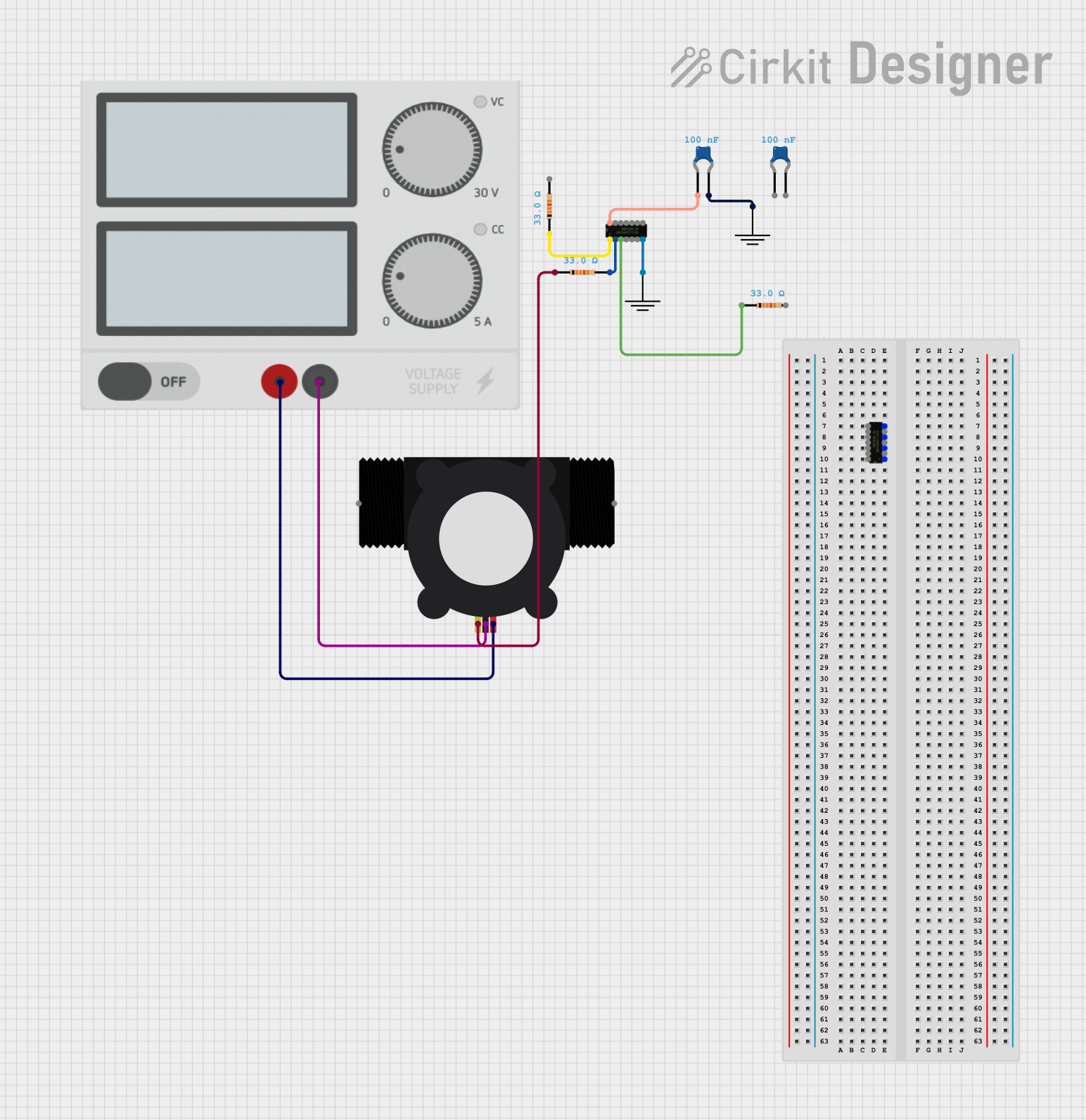

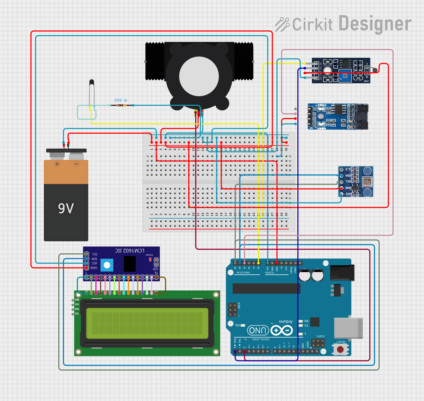
Explore Projects Built with Flow sensor YF-B7
Technical Specifications
Below are the key technical details of the YF-B7 flow sensor:
| Parameter | Value |
|---|---|
| Operating Voltage | 5V to 18V DC |
| Output Signal | Pulse (Square Wave) |
| Flow Rate Range | 1 to 30 L/min |
| Accuracy | ±5% |
| Maximum Working Pressure | ≤1.75 MPa |
| Operating Temperature | -25°C to 80°C |
| Pulse Frequency Formula | Flow Rate (L/min) = Pulse Frequency / 7.5 |
| Connector Type | 3-pin JST |
| Material | Plastic (Nylon) |
Pin Configuration
The YF-B7 flow sensor has a 3-pin JST connector. The pinout is as follows:
| Pin | Name | Description |
|---|---|---|
| 1 | VCC | Power supply input (5V to 18V DC) |
| 2 | GND | Ground connection |
| 3 | Signal | Pulse output signal (connect to microcontroller pin) |
Usage Instructions
How to Use the YF-B7 in a Circuit
- Power Supply: Connect the VCC pin to a 5V to 18V DC power source. Ensure the power supply is stable and within the specified range.
- Ground Connection: Connect the GND pin to the ground of your circuit.
- Signal Output: Connect the Signal pin to a digital input pin on your microcontroller. Use a pull-up resistor (e.g., 10kΩ) if required by your microcontroller.
Important Considerations
- Flow Direction: Ensure the liquid flows in the direction indicated by the arrow on the sensor body.
- Debris Filtering: Use a filter to prevent debris from entering the sensor, as this can damage the rotor or affect accuracy.
- Pulse Reading: The sensor outputs a square wave signal. The frequency of the pulses corresponds to the flow rate. Use the formula
Flow Rate (L/min) = Pulse Frequency / 7.5to calculate the flow rate. - Temperature and Pressure: Do not exceed the specified operating temperature and pressure limits to avoid damaging the sensor.
Example Code for Arduino UNO
Below is an example of how to use the YF-B7 flow sensor with an Arduino UNO to measure and display the flow rate:
// YF-B7 Flow Sensor Example Code for Arduino UNO
// Measures and displays the flow rate in liters per minute (L/min)

volatile int pulseCount = 0; // Variable to store pulse count
float flowRate = 0.0;        // Variable to store flow rate
unsigned long lastTime = 0;  // Variable to store the last time measurement
const int sensorPin = 2;     // Pin connected to the Signal pin of the sensor

void setup() {
  pinMode(sensorPin, INPUT_PULLUP); // Set sensor pin as input with pull-up
  attachInterrupt(digitalPinToInterrupt(sensorPin), pulseCounter, RISING);
  Serial.begin(9600); // Initialize serial communication
}

void loop() {
  unsigned long currentTime = millis();

  // Calculate flow rate every second
  if (currentTime - lastTime >= 1000) {
    detachInterrupt(digitalPinToInterrupt(sensorPin)); // Disable interrupt
    flowRate = (pulseCount / 7.5); // Calculate flow rate in L/min
    Serial.print("Flow Rate: ");
    Serial.print(flowRate);
    Serial.println(" L/min");
    pulseCount = 0; // Reset pulse count
    lastTime = currentTime; // Update last time
    attachInterrupt(digitalPinToInterrupt(sensorPin), pulseCounter, RISING);
  }
}

// Interrupt service routine to count pulses
void pulseCounter() {
  pulseCount++;
}
Notes:
- Ensure the sensor is properly connected to avoid incorrect readings.
- The
INPUT_PULLUPmode is used to ensure a stable signal from the sensor.
Troubleshooting and FAQs
Common Issues
No Output Signal:
- Cause: Incorrect wiring or insufficient power supply.
- Solution: Verify the connections and ensure the power supply is within the specified range.
Inaccurate Flow Rate:
- Cause: Debris in the sensor or incorrect pulse frequency calculation.
- Solution: Clean the sensor and ensure the formula
Flow Rate = Pulse Frequency / 7.5is used.
Sensor Not Responding:
- Cause: Damaged rotor or sensor.
- Solution: Inspect the sensor for physical damage and replace if necessary.
FAQs
Can the YF-B7 measure other liquids besides water?
- The YF-B7 is designed for water. Using it with other liquids may affect accuracy or damage the sensor.
What is the maximum cable length for the sensor?
- The maximum cable length depends on the environment and signal integrity. For best results, keep the cable length under 1 meter.
Can I use the YF-B7 with a 3.3V microcontroller?
- Yes, but you may need a level shifter or voltage divider to ensure compatibility with the 3.3V logic level.
By following this documentation, you can effectively integrate the YF-B7 flow sensor into your projects and troubleshoot common issues.