How to Use Boost Converter: Examples, Pinouts, and Specs
Introduction
A Boost Converter is a type of DC-DC converter that steps up (increases) the input voltage to a higher output voltage while maintaining power balance. It is widely used in applications where the input voltage is lower than the required output voltage. This component is essential in battery-powered devices, renewable energy systems, and portable electronics to enhance voltage levels efficiently.
Explore Projects Built with Boost Converter
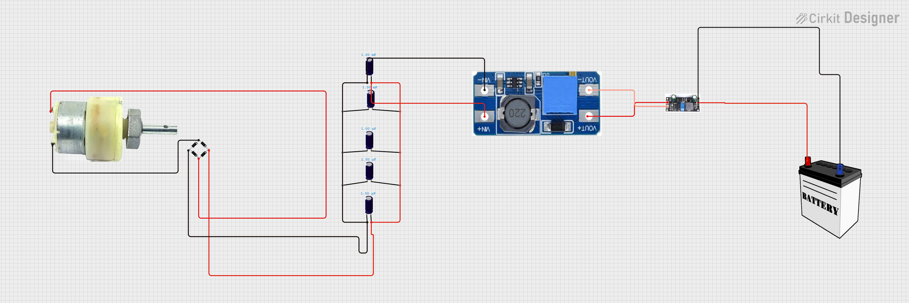


Explore Projects Built with Boost Converter
Common Applications and Use Cases
- Powering high-voltage devices from low-voltage batteries
- Solar power systems to regulate and step up voltage
- LED drivers for consistent brightness
- Electric vehicles to manage battery voltage
- Portable chargers and power banks
Technical Specifications
Below are the general technical specifications of a typical Boost Converter. Note that specific values may vary depending on the model and manufacturer.
| Parameter | Specification |
|---|---|
| Input Voltage Range | 2V to 36V |
| Output Voltage Range | 5V to 60V |
| Output Current | Up to 10A (depending on the model) |
| Efficiency | Up to 95% |
| Switching Frequency | 100 kHz to 1 MHz |
| Operating Temperature | -40°C to +85°C |
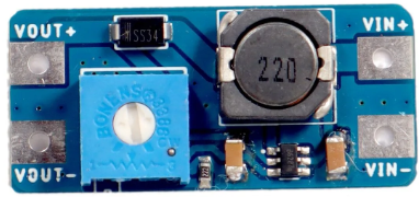
Pin Configuration and Descriptions
The pinout of a Boost Converter module may vary, but a common configuration is as follows:
| Pin Name | Description |
|---|---|
| VIN | Input voltage pin (connect to the power source) |
| GND | Ground pin (common ground for input and output) |
| VOUT | Output voltage pin (connect to the load) |
| EN (optional) | Enable pin (used to turn the module on/off) |
| FB (optional) | Feedback pin (used for voltage regulation) |
Usage Instructions
How to Use the Boost Converter in a Circuit
Connect the Input Voltage (VIN):
Attach the positive terminal of your power source (e.g., battery) to the VIN pin and the negative terminal to the GND pin.Set the Output Voltage (if adjustable):
Many Boost Converters have a potentiometer to adjust the output voltage. Use a multimeter to measure the output voltage and turn the potentiometer until the desired voltage is achieved.Connect the Load to VOUT:
Attach the positive terminal of your load to the VOUT pin and the negative terminal to the GND pin.Enable the Module (if applicable):
If the module has an EN (Enable) pin, ensure it is connected to a HIGH signal (or left floating, depending on the module) to activate the converter.
Important Considerations and Best Practices
- Input Voltage Range: Ensure the input voltage is within the specified range of the Boost Converter to avoid damage.
- Output Voltage Limit: Do not exceed the maximum output voltage rating of the module.
- Heat Dissipation: High current applications may cause the module to heat up. Use a heatsink or active cooling if necessary.
- Capacitor Selection: Use appropriate input and output capacitors to reduce voltage ripple and improve stability.
- Load Requirements: Ensure the load does not draw more current than the module's rated output current.
Example: Using a Boost Converter with Arduino UNO
Below is an example of using a Boost Converter to power an Arduino UNO from a 3.7V Li-ion battery by stepping up the voltage to 9V.
Circuit Connections
- Connect the positive terminal of the Li-ion battery to the VIN pin of the Boost Converter.
- Connect the negative terminal of the battery to the GND pin of the Boost Converter.
- Adjust the Boost Converter's output voltage to 9V using a multimeter and the onboard potentiometer.
- Connect the VOUT pin of the Boost Converter to the Arduino UNO's VIN pin.
- Connect the GND pin of the Boost Converter to the Arduino UNO's GND pin.
Arduino Code Example
// Example code to blink an LED connected to pin 13 of Arduino UNO
// Ensure the Arduino is powered via the Boost Converter at 9V

void setup() {
  pinMode(13, OUTPUT); // Set pin 13 as an output pin
}

void loop() {
  digitalWrite(13, HIGH); // Turn the LED on
  delay(1000);            // Wait for 1 second
  digitalWrite(13, LOW);  // Turn the LED off
  delay(1000);            // Wait for 1 second
}
Troubleshooting and FAQs
Common Issues and Solutions
No Output Voltage:
- Check the input voltage and ensure it is within the specified range.
- Verify all connections, especially VIN, GND, and VOUT.
- If the module has an EN pin, ensure it is enabled (HIGH or floating).
Output Voltage is Unstable:
- Add input and output capacitors to reduce voltage ripple.
- Ensure the load is not exceeding the module's current rating.
Module Overheating:
- Reduce the load current or use a heatsink for better heat dissipation.
- Check for short circuits or incorrect wiring.
Cannot Adjust Output Voltage:
- Verify that the potentiometer is functional and not damaged.
- Ensure the input voltage is sufficient to achieve the desired output voltage.
FAQs
Q: Can I use a Boost Converter to power a 12V device from a 5V USB source?
A: Yes, as long as the Boost Converter supports a 5V input and can step up to 12V with sufficient current for your device.
Q: What happens if I reverse the input polarity?
A: Most Boost Converters do not have reverse polarity protection. Reversing the input polarity can damage the module. Always double-check your connections.
Q: Can I use a Boost Converter with a solar panel?
A: Yes, Boost Converters are commonly used with solar panels to step up and regulate the voltage. Ensure the input voltage and current are within the module's specifications.
Q: How do I calculate the efficiency of the Boost Converter?
A: Efficiency (%) = (Output Power / Input Power) × 100. Measure the input and output voltage and current to calculate power.
By following this documentation, you can effectively use a Boost Converter in your projects and troubleshoot common issues.