
How to Use AD8561 - Ultrafast 7ns Single Supply Comparator: Examples, Pinouts, and Specs
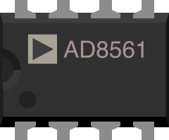
 Design with AD8561 - Ultrafast 7ns Single Supply Comparator in Cirkit Designer
Introduction
The AD8561 is a high-speed comparator manufactured by Analog Devices. It is designed for single-supply operation and features an ultrafast response time of 7 nanoseconds, making it ideal for applications requiring rapid signal processing. The AD8561 operates with low power consumption and provides high precision, ensuring reliable performance in demanding environments.
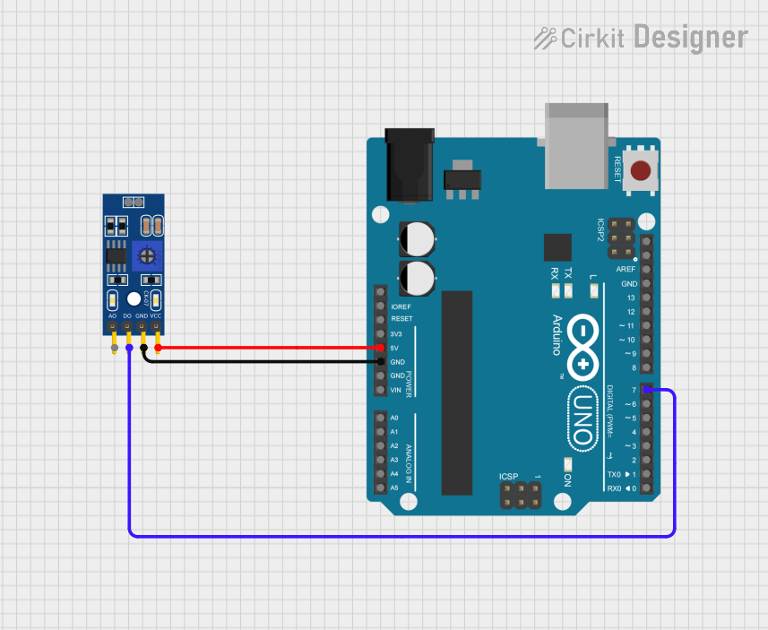
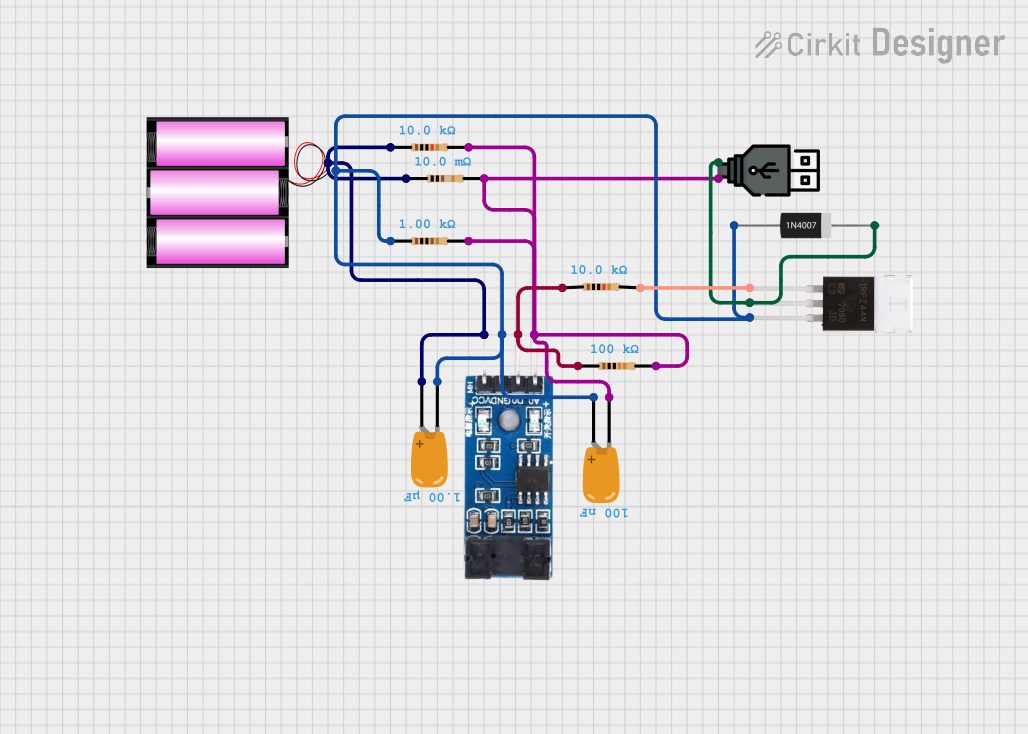
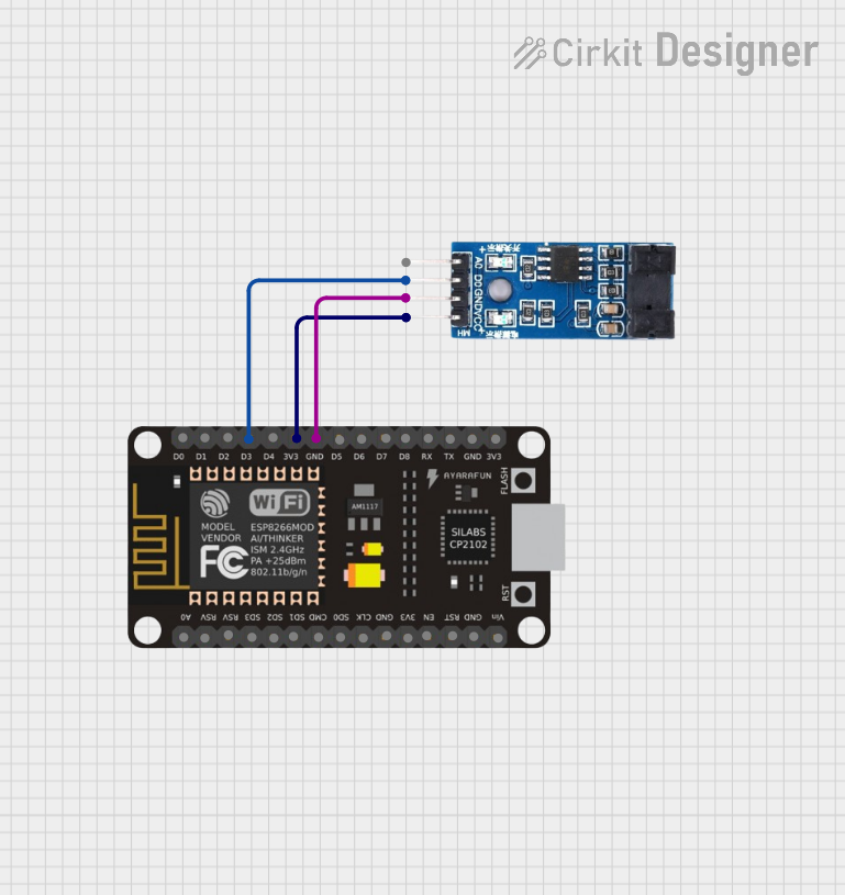
Explore Projects Built with AD8561 - Ultrafast 7ns Single Supply Comparator
 Open Project in Cirkit Designer
 Open Project in Cirkit Designer
 Open Project in Cirkit Designer
 Open Project in Cirkit Designer
Explore Projects Built with AD8561 - Ultrafast 7ns Single Supply Comparator
Open Project in Cirkit DesignerOpen Project in Cirkit DesignerOpen Project in Cirkit DesignerOpen Project in Cirkit DesignerCommon Applications and Use Cases
- Signal Conditioning: Enhancing and preparing analog signals for further processing.
- Level Detection: Detecting voltage thresholds in circuits.
- High-Speed Analog-to-Digital Conversion: Acting as a front-end for ADCs.
- Pulse Width Modulation (PWM) Circuits: Generating or detecting PWM signals.
- Zero-Crossing Detectors: Identifying when a signal crosses a reference voltage.
- Oscillators and Timing Circuits: Used in clock generation and timing applications.
Technical Specifications
Key Technical Details
| Parameter | Value |
|---|---|
| Supply Voltage Range | 2.7 V to 5.5 V |
| Input Offset Voltage | ±2 mV (typical) |
| Propagation Delay | 7 ns (typical) |
| Input Bias Current | 1 µA (typical) |
| Output Voltage Swing | 0.1 V to (Vcc - 0.1 V) |
| Output Drive Capability | ±40 mA |
| Operating Temperature Range | -40°C to +85°C |
| Package Options | 8-lead SOIC, 8-lead PDIP |
Pin Configuration and Descriptions
The AD8561 is available in an 8-pin package. Below is the pinout and description:
| Pin Number | Pin Name | Description |
|---|---|---|
| 1 | OUT | Comparator output |
| 2 | V+ | Positive power supply (2.7 V to 5.5 V) |
| 3 | IN+ | Non-inverting input |
| 4 | IN- | Inverting input |
| 5 | GND | Ground |
| 6 | NC | No connection (leave unconnected) |
| 7 | NC | No connection (leave unconnected) |
| 8 | V- | Negative power supply (typically GND for single supply) |
Usage Instructions
How to Use the AD8561 in a Circuit
- Power Supply: Connect the V+ pin to a power supply within the range of 2.7 V to 5.5 V. Connect the V- pin to ground (GND) for single-supply operation.
- Input Configuration:
- Connect the signal to be compared to the IN+ (non-inverting input) or IN- (inverting input), depending on the desired polarity of the output.
- Use a reference voltage on the other input pin for comparison.
- Output Connection: The OUT pin provides the comparator's output. It can directly drive digital logic or other circuitry.
- Bypass Capacitor: Place a decoupling capacitor (e.g., 0.1 µF) close to the V+ pin to reduce noise and ensure stable operation.
- Pull-Up Resistor (Optional): If the output is connected to a high-impedance load, consider using a pull-up resistor to ensure proper logic levels.
Important Considerations and Best Practices
- Input Voltage Range: Ensure the input voltages remain within the specified range to avoid damage or incorrect operation.
- Hysteresis: To prevent output oscillations due to noise, consider adding hysteresis by connecting a resistor between the output and one of the input pins.
- PCB Layout: Use a clean and low-noise PCB layout. Keep input traces short and away from noisy signals.
- Thermal Management: Operate the device within the specified temperature range to maintain performance.
Example: Using AD8561 with Arduino UNO
The AD8561 can be used with an Arduino UNO for level detection. Below is an example circuit and code:
Circuit Description
- Connect the V+ pin of the AD8561 to the Arduino's 5V pin.
- Connect the V- pin to the Arduino's GND.
- Connect the OUT pin to a digital input pin on the Arduino (e.g., pin 2).
- Apply the signal to be compared to the IN+ pin and a reference voltage to the IN- pin.
Arduino Code
// Example code for using AD8561 with Arduino UNO
const int comparatorOutputPin = 2; // AD8561 OUT pin connected to Arduino pin 2
const int ledPin = 13;             // Built-in LED for visual indication

void setup() {
  pinMode(comparatorOutputPin, INPUT); // Set comparator output pin as input
  pinMode(ledPin, OUTPUT);            // Set LED pin as output
  Serial.begin(9600);                 // Initialize serial communication
}

void loop() {
  int comparatorState = digitalRead(comparatorOutputPin); // Read comparator output

  if (comparatorState == HIGH) {
    digitalWrite(ledPin, HIGH); // Turn on LED if output is HIGH
    Serial.println("Comparator Output: HIGH");
  } else {
    digitalWrite(ledPin, LOW);  // Turn off LED if output is LOW
    Serial.println("Comparator Output: LOW");
  }

  delay(100); // Small delay for stability
}
Troubleshooting and FAQs
Common Issues and Solutions
No Output Signal:
- Verify that the power supply is connected and within the specified range.
- Check the input signal and reference voltage connections.
- Ensure the output is not overloaded or shorted.
Output Oscillations:
- Add hysteresis by connecting a resistor between the output and one of the input pins.
- Ensure the input signal is clean and free from noise.
Incorrect Output Levels:
- Verify that the output is not driving a load beyond its capability (±40 mA).
- Check for proper pull-up or pull-down resistors if required.
Device Overheating:
- Ensure the device is operating within the specified voltage and temperature ranges.
- Check for excessive current draw on the output.
FAQs
Q1: Can the AD8561 operate with a dual power supply?
A1: Yes, the AD8561 can operate with a dual power supply. However, it is optimized for single-supply operation. For dual supply, connect V+ to the positive voltage and V- to the negative voltage.
Q2: What is the maximum input voltage range?
A2: The input voltage range is from 0 V to V+ - 1.5 V. Ensure the input signals remain within this range.
Q3: Can the AD8561 drive an LED directly?
A3: Yes, the AD8561 can drive an LED directly, provided the current does not exceed its output drive capability of ±40 mA.
Q4: How can I add hysteresis to the comparator?
A4: Connect a resistor between the output pin and one of the input pins. This creates positive feedback, introducing hysteresis to stabilize the output.
By following this documentation, users can effectively integrate the AD8561 into their designs and troubleshoot common issues.