How to Use Rocker Switch: Examples, Pinouts, and Specs
Introduction
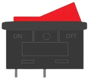
A rocker switch is a type of on/off electrical switch that operates by rocking a small lever back and forth. This action either opens or closes the circuit. Rocker switches are commonly used in a variety of applications, including household appliances, office equipment, industrial machinery, and automotive electronics, due to their ease of use and durability.
Explore Projects Built with Rocker Switch

Explore Projects Built with Rocker Switch
Technical Specifications
General Characteristics
- Switch Type: Rocker
- Action: SPST (Single Pole, Single Throw), DPST (Double Pole, Single Throw), SPDT (Single Pole, Double Throw), DPDT (Double Pole, Double Throw), etc.
- Current Rating: Typically ranges from 3A to 20A
- Voltage Rating: Commonly up to 250V AC
- Contact Resistance: Varies by model, often less than 50 mΩ
- Insulation Resistance: Typically greater than 100 MΩ
- Operating Temperature: Varies by model, often -20°C to +85°C
Pin Configuration and Descriptions
| Pin Number | Description | Note |
|---|---|---|
| 1 | Input/Output (depending on type) | Connected to power source or load |
| 2 | Output/Input (depending on type) | Connected to load or power source |
| 3 | Ground (if applicable) | Only present in lighted rocker switch |
Note: The pin configuration may vary depending on the type of rocker switch (SPST, DPST, SPDT, DPDT, etc.).
Usage Instructions
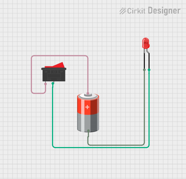
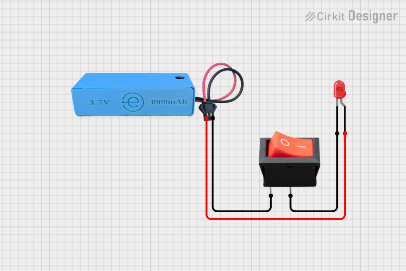
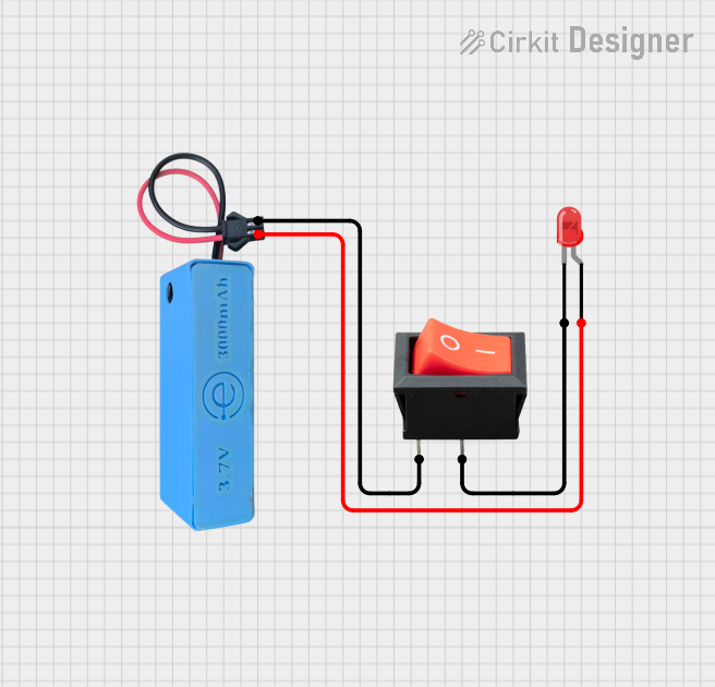
Integration into a Circuit
- Identify the Type of Rocker Switch: Determine whether you have an SPST, DPST, SPDT, or DPDT switch, as this will dictate how you integrate it into your circuit.
- Power Source Connection: Connect one of the pins (refer to the pin configuration table) to the power source.
- Load Connection: Connect another pin to the load you wish to control.
- Grounding (if applicable): If the rocker switch includes a ground pin, typically for an integrated light, connect it to the system ground.
Best Practices
- Current Rating: Ensure the current rating of the switch exceeds the maximum current expected in the circuit.
- Voltage Rating: Verify that the voltage rating is suitable for your application.
- Mounting: Secure the switch firmly to prevent movement, which could lead to intermittent connections.
- Wiring: Use appropriately rated and insulated wires to prevent electrical hazards.
Troubleshooting and FAQs
Common Issues
- Switch Does Not Operate: Check for proper wiring and ensure that the switch is not damaged.
- Intermittent Operation: Verify that the switch is mounted securely and that there are no loose connections.
- Light Does Not Illuminate (if applicable): Ensure that the ground pin is connected and that the bulb (if replaceable) is functional.
FAQs
Q: Can I use a rocker switch with a DC circuit? A: Yes, rocker switches can be used with both AC and DC circuits. Ensure the DC voltage and current do not exceed the switch's ratings.
Q: How do I know if my rocker switch is on or off? A: Most rocker switches have a clear on/off indication, often by the position of the lever or an illuminated indicator when in the on position.
Q: Is it possible to replace the light inside a lighted rocker switch? A: This depends on the design of the switch. Some switches have integrated lights that are not user-replaceable, while others may allow for bulb replacement.
Example Code for Arduino UNO
If you're using a rocker switch to control a device with an Arduino UNO, here's a simple example code that demonstrates how to read the state of the switch:
// Define the pin connected to the rocker switch
const int rockerSwitchPin = 2;

void setup() {
  // Set the rocker switch pin as an input
  pinMode(rockerSwitchPin, INPUT);
  // Initialize serial communication at 9600 bits per second
  Serial.begin(9600);
}

void loop() {
  // Read the state of the rocker switch
  int switchState = digitalRead(rockerSwitchPin);

  // Print the state of the switch to the Serial Monitor
  Serial.println(switchState);

  // Delay for a bit to avoid spamming the Serial Monitor
  delay(500);
}
In this example, the Arduino reads the state of the rocker switch connected to pin 2 and prints the state to the Serial Monitor. The switch is assumed to be wired such that it connects the pin to ground when in the "on" position, using the Arduino's internal pull-up resistor.