How to Use ESP32 Wroom 32: Examples, Pinouts, and Specs
Introduction
The ESP32 Wroom 32 is a powerful microcontroller module manufactured by Arduino, featuring integrated Wi-Fi and Bluetooth capabilities. It is designed for Internet of Things (IoT) applications and projects that require wireless connectivity. With its dual-core processor, low power consumption, and extensive GPIO options, the ESP32 Wroom 32 is a versatile solution for a wide range of embedded systems.
Explore Projects Built with ESP32 Wroom 32


Explore Projects Built with ESP32 Wroom 32
Common Applications and Use Cases
- IoT devices and smart home automation
- Wireless sensor networks
- Wearable technology
- Industrial automation
- Robotics and drones
- Real-time data monitoring and logging
Technical Specifications
The ESP32 Wroom 32 module is packed with features that make it suitable for both simple and complex projects. Below are its key technical specifications:
| Parameter | Value |
|---|---|
| Microcontroller | Tensilica Xtensa LX6 Dual-Core (240 MHz) |
| Flash Memory | 4 MB |
| SRAM | 520 KB |
| Wi-Fi | 802.11 b/g/n (2.4 GHz) |
| Bluetooth | v4.2 BR/EDR and BLE |
| Operating Voltage | 3.3V |
| Input Voltage Range | 3.0V - 3.6V |
| GPIO Pins | 34 |
| ADC Channels | 18 (12-bit resolution) |
| DAC Channels | 2 (8-bit resolution) |
| UART Interfaces | 3 |
| SPI Interfaces | 4 |
| I2C Interfaces | 2 |
| PWM Channels | 16 |
| Power Consumption | 5 µA (deep sleep), 240 mA (active Wi-Fi) |
| Dimensions | 25.5 mm x 18 mm |
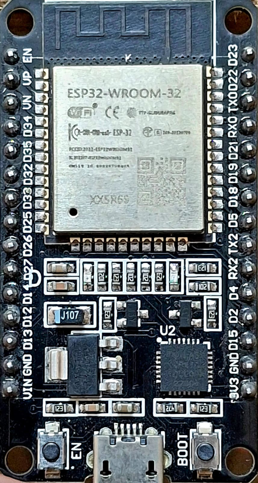
Pin Configuration and Descriptions
The ESP32 Wroom 32 module has a total of 38 pins. Below is a table describing the key pins:
| Pin | Name | Description |
|---|---|---|
| 1 | EN | Enable pin. Active high to enable the module. |
| 2 | IO0 | GPIO0. Used for boot mode selection. |
| 3 | IO2 | GPIO2. General-purpose I/O pin. |
| 4 | IO4 | GPIO4. General-purpose I/O pin. |
| 5 | IO5 | GPIO5. General-purpose I/O pin. |
| 6 | IO12 | GPIO12. General-purpose I/O pin. |
| 7 | IO13 | GPIO13. General-purpose I/O pin. |
| 8 | IO14 | GPIO14. General-purpose I/O pin. |
| 9 | IO15 | GPIO15. General-purpose I/O pin. |
| 10 | IO16 | GPIO16. General-purpose I/O pin. |
| 11 | IO17 | GPIO17. General-purpose I/O pin. |
| 12 | GND | Ground pin. |
| 13 | 3V3 | 3.3V power supply pin. |
| 14 | VIN | Input voltage pin (3.0V - 3.6V). |
For a complete pinout diagram, refer to the official Arduino documentation.
Usage Instructions
How to Use the ESP32 Wroom 32 in a Circuit
- Powering the Module: Connect the VIN pin to a 3.3V power source. Ensure the power supply can provide sufficient current (at least 500 mA).
- Connecting to a Microcontroller: Use the UART, SPI, or I2C interfaces to communicate with other devices. For standalone operation, program the ESP32 directly using the Arduino IDE.
- Programming: The ESP32 can be programmed via USB using a serial-to-USB adapter. Select "ESP32 Dev Module" in the Arduino IDE and upload your code.
- Wi-Fi and Bluetooth Setup: Use the built-in libraries (
WiFi.handBluetoothSerial.h) to configure wireless connectivity.
Important Considerations and Best Practices
- Voltage Levels: The ESP32 operates at 3.3V logic levels. Avoid connecting 5V signals directly to its pins.
- Boot Mode: To enter boot mode for programming, hold the IO0 pin low while resetting the module.
- Antenna Placement: Ensure the onboard antenna is not obstructed by metal objects to maintain optimal wireless performance.
- Power Supply: Use a stable power source to avoid unexpected resets or performance issues.
Example Code for Arduino IDE
Below is an example of how to connect the ESP32 Wroom 32 to a Wi-Fi network and blink an LED:
#include <WiFi.h> // Include the Wi-Fi library

const char* ssid = "Your_SSID";       // Replace with your Wi-Fi SSID
const char* password = "Your_PASSWORD"; // Replace with your Wi-Fi password
const int ledPin = 2;                 // GPIO2 is connected to the onboard LED

void setup() {
  pinMode(ledPin, OUTPUT);            // Set the LED pin as an output
  Serial.begin(115200);               // Start the serial communication
  Serial.println("Connecting to Wi-Fi...");

  WiFi.begin(ssid, password);         // Connect to the Wi-Fi network
  while (WiFi.status() != WL_CONNECTED) {
    delay(500);                       // Wait for the connection to establish
    Serial.print(".");
  }
  Serial.println("\nWi-Fi connected!");
  Serial.print("IP Address: ");
  Serial.println(WiFi.localIP());     // Print the device's IP address
}

void loop() {
  digitalWrite(ledPin, HIGH);         // Turn the LED on
  delay(1000);                        // Wait for 1 second
  digitalWrite(ledPin, LOW);          // Turn the LED off
  delay(1000);                        // Wait for 1 second
}
Troubleshooting and FAQs
Common Issues and Solutions
The ESP32 is not detected by the Arduino IDE:
- Ensure the correct board ("ESP32 Dev Module") is selected in the Tools menu.
- Install the ESP32 board package in the Arduino IDE via the Board Manager.
- Check the USB cable and port for proper connection.
Wi-Fi connection fails:
- Double-check the SSID and password in your code.
- Ensure the Wi-Fi network is within range and not using unsupported security protocols.
Module resets unexpectedly:
- Verify that the power supply provides sufficient current (at least 500 mA).
- Check for loose connections or short circuits in your circuit.
Bluetooth is not discoverable:
- Ensure the Bluetooth feature is initialized correctly in your code.
- Check for interference from other wireless devices.
FAQs
Q: Can the ESP32 Wroom 32 operate on 5V?
A: No, the ESP32 operates at 3.3V. Applying 5V to its pins may damage the module.
Q: How do I update the firmware on the ESP32?
A: Use the Arduino IDE or the ESP32 Flash Download Tool to upload new firmware.
Q: Can I use the ESP32 for battery-powered projects?
A: Yes, the ESP32 supports low-power modes such as deep sleep, making it suitable for battery-powered applications.
Q: Is the ESP32 compatible with Arduino libraries?
A: Yes, many Arduino libraries are compatible with the ESP32, but some may require modifications.