How to Use INA226: Examples, Pinouts, and Specs
Introduction
The INA226, manufactured by Sensor, is a high-side current shunt monitor with an integrated I2C interface. It is designed to measure voltage, current, and power with high precision, thanks to its built-in analog-to-digital converter (ADC). The INA226 is highly versatile and operates over a wide voltage range, making it ideal for applications such as battery management, power monitoring, and energy-efficient system design.
Explore Projects Built with INA226

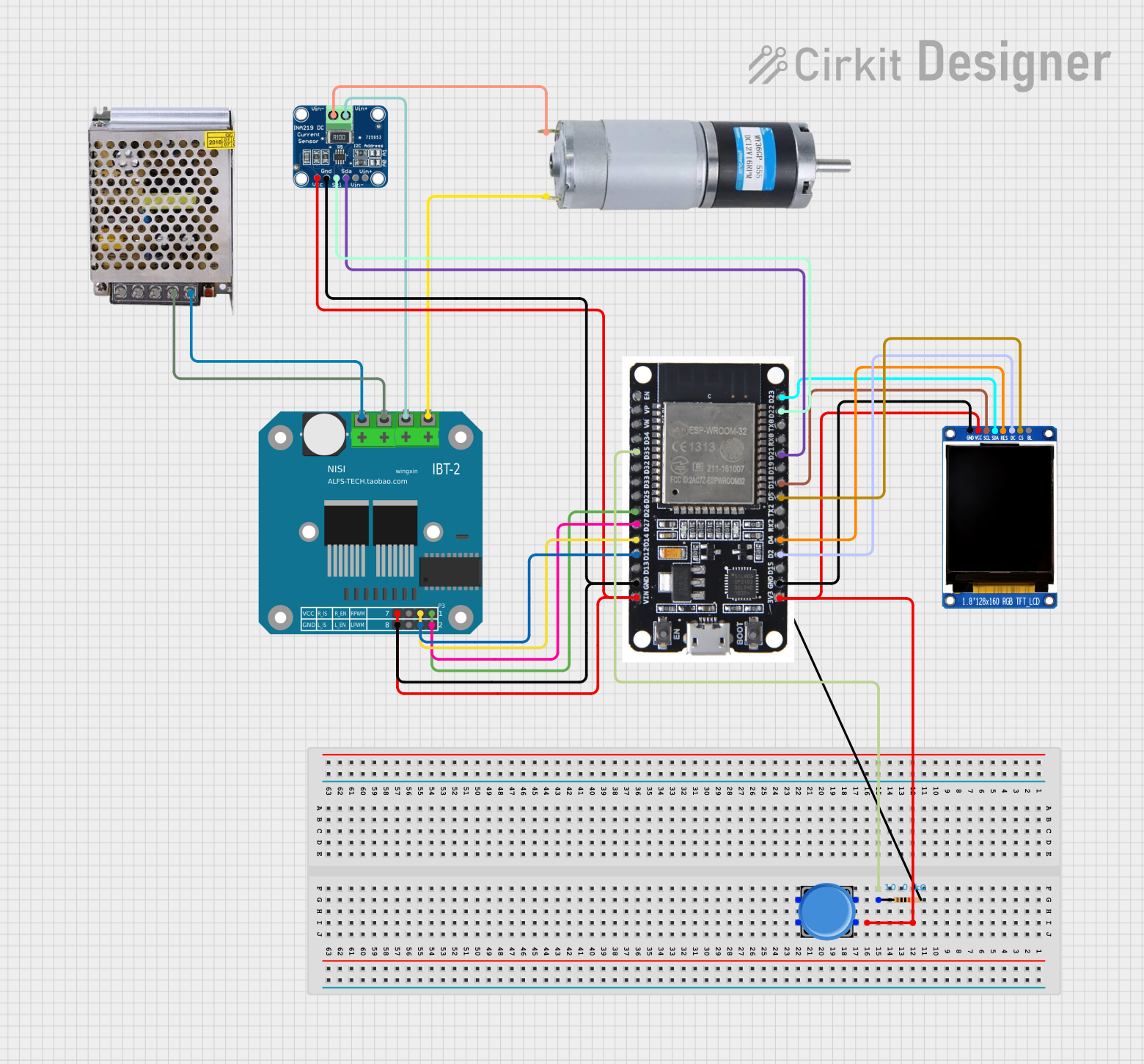


Explore Projects Built with INA226
Common Applications
- Battery management systems
- Power supply monitoring
- Energy metering in IoT devices
- Industrial automation and control
- Solar power systems
Technical Specifications
Key Technical Details
| Parameter | Value |
|---|---|
| Supply Voltage (Vcc) | 2.7V to 5.5V |
| Input Voltage Range | 0V to 36V |
| Current Measurement Range | Configurable (based on shunt resistor) |
| Power Measurement | Calculated internally (Voltage × Current) |
| Communication Interface | I2C (up to 400 kHz) |
| ADC Resolution | 16-bit |
| Operating Temperature | -40°C to +125°C |
| Package | MSOP-10 |
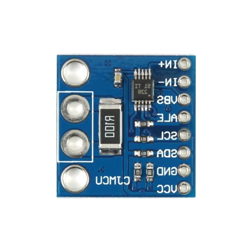
Pin Configuration and Descriptions
| Pin No. | Pin Name | Description |
|---|---|---|
| 1 | VBUS | Voltage input to measure bus voltage |
| 2 | GND | Ground |
| 3 | SCL | I2C clock line |
| 4 | SDA | I2C data line |
| 5 | ALERT/RDY | Alert or Ready output (configurable) |
| 6 | V+ | Power supply input (2.7V to 5.5V) |
| 7 | A0 | I2C address selection bit 0 |
| 8 | A1 | I2C address selection bit 1 |
| 9 | SHUNT+ | Positive input for shunt resistor |
| 10 | SHUNT- | Negative input for shunt resistor |
Usage Instructions
How to Use the INA226 in a Circuit
- Power Supply: Connect the V+ pin to a 2.7V to 5.5V power source and GND to ground.
- Shunt Resistor: Place a shunt resistor between the SHUNT+ and SHUNT- pins to measure current. The value of the resistor depends on the expected current range.
- Voltage Measurement: Connect the VBUS pin to the voltage source you want to monitor.
- I2C Communication: Connect the SCL and SDA pins to the corresponding I2C lines of your microcontroller. Use pull-up resistors (typically 4.7kΩ) on these lines.
- Address Configuration: Set the A0 and A1 pins to configure the I2C address. These pins can be connected to V+ or GND to select one of 16 possible addresses.
- Alert/Ready Pin: Optionally, use the ALERT/RDY pin for interrupt-driven alerts or to indicate data readiness.
Important Considerations and Best Practices
- Shunt Resistor Selection: Choose a low-value, high-precision resistor to minimize power loss and ensure accurate current measurements.
- I2C Pull-Up Resistors: Ensure proper pull-up resistors are used on the I2C lines to maintain signal integrity.
- Bypass Capacitor: Place a 0.1µF ceramic capacitor close to the V+ pin to filter noise.
- Address Conflicts: If multiple INA226 devices are used on the same I2C bus, ensure each has a unique address by configuring the A0 and A1 pins.
Example Code for Arduino UNO
#include <Wire.h>

// INA226 I2C address (default: A0 = GND, A1 = GND)
#define INA226_ADDRESS 0x40

// Register addresses
#define CONFIG_REGISTER 0x00
#define BUS_VOLTAGE_REGISTER 0x02
#define CURRENT_REGISTER 0x04

void setup() {
  Wire.begin(); // Initialize I2C communication
  Serial.begin(9600); // Initialize serial communication for debugging

  // Configure INA226 (example configuration)
  Wire.beginTransmission(INA226_ADDRESS);
  Wire.write(CONFIG_REGISTER); // Point to configuration register
  Wire.write(0x45); // MSB: Set averaging, bus voltage conversion time
  Wire.write(0x27); // LSB: Set shunt voltage conversion time
  Wire.endTransmission();
}

void loop() {
  // Read bus voltage
  Wire.beginTransmission(INA226_ADDRESS);
  Wire.write(BUS_VOLTAGE_REGISTER); // Point to bus voltage register
  Wire.endTransmission();

  Wire.requestFrom(INA226_ADDRESS, 2); // Request 2 bytes
  if (Wire.available() == 2) {
    uint16_t rawVoltage = (Wire.read() << 8) | Wire.read();
    float busVoltage = rawVoltage * 0.00125; // Convert to volts (1.25mV/LSB)
    Serial.print("Bus Voltage: ");
    Serial.print(busVoltage);
    Serial.println(" V");
  }

  delay(1000); // Wait 1 second before next reading
}
Troubleshooting and FAQs
Common Issues and Solutions
No I2C Communication:
- Ensure the INA226 is powered correctly (V+ and GND connected).
- Verify pull-up resistors are present on the SCL and SDA lines.
- Check the I2C address configuration (A0 and A1 pins).
Incorrect Current or Voltage Readings:
- Verify the shunt resistor value and connections.
- Ensure the VBUS pin is connected to the correct voltage source.
- Check for noise or interference on the measurement lines.
ALERT/RDY Pin Not Functioning:
- Confirm the ALERT/RDY pin is configured correctly in the INA226 registers.
- Ensure the microcontroller's interrupt pin is properly connected.
FAQs
Q: Can the INA226 measure negative currents?
A: No, the INA226 is designed for high-side current sensing and measures only positive currents.Q: What is the maximum current the INA226 can measure?
A: The maximum current depends on the shunt resistor value and the voltage drop across it. Ensure the voltage drop does not exceed the ADC's input range.Q: Can I use the INA226 with a 3.3V microcontroller?
A: Yes, the INA226 operates with a supply voltage as low as 2.7V, making it compatible with 3.3V systems.