Cirkit Designer Logo
Cirkit Designer
Your all-in-one circuit design IDE
Home / 
Component Documentation

How to Use Red Cap Pushbutton: Examples, Pinouts, and Specs

Image of Red Cap Pushbutton
Cirkit Designer LogoDesign with Red Cap Pushbutton in Cirkit Designer

Introduction

The Red Cap Pushbutton is a momentary switch that is activated when pressed. It is commonly used for user input in electronic devices, where the red cap often signifies a specific function, such as "stop" or "emergency." This component is widely utilized in control panels, DIY electronics projects, and industrial systems due to its simplicity and reliability.

Explore Projects Built with Red Cap Pushbutton

Use Cirkit Designer to design, explore, and prototype these projects online. Some projects support real-time simulation. Click "Open Project" to start designing instantly!
Battery-Powered RGB LED Control with Pushbuttons
Image of EXP-12 E: A project utilizing Red Cap Pushbutton in a practical application
This circuit consists of an RGB LED controlled by three pushbuttons, each corresponding to one of the LED's color channels (Red, Green, and Blue). The pushbuttons are powered by a MAHIR 1.mini power source, allowing the user to manually toggle each color channel of the RGB LED.
Cirkit Designer LogoOpen Project in Cirkit Designer
Pushbutton-Controlled Dual-Color LED Circuit with TA6568
Image of polarity detector: A project utilizing Red Cap Pushbutton in a practical application
This is a pushbutton-controlled LED circuit with a TA6568 chip that likely drives two LEDs (red and green). Each LED is connected to a pushbutton through the TA6568, allowing the user to toggle the state of the LEDs. The circuit is powered by a 3V battery and includes a JST connector for external interfacing.
Cirkit Designer LogoOpen Project in Cirkit Designer
Battery-Powered LED Circuit with Pushbutton Control and Capacitance Smoothing
Image of Coding and Robotics activity 3: A project utilizing Red Cap Pushbutton in a practical application
This circuit consists of a 4 x AAA battery mount providing power, two pushbuttons acting as switches, an electrolytic capacitor for smoothing voltage fluctuations, and a red LED as an indicator. The LED lights up when either pushbutton is pressed, with the capacitor likely serving to debounce the pushbutton signal or provide a more stable LED operation. There is no microcontroller in this circuit, indicating a simple, direct-control user interface.
Cirkit Designer LogoOpen Project in Cirkit Designer
Pushbutton-Controlled LED Circuit with Capacitor Smoothing
Image of cirkit designer project3: A project utilizing Red Cap Pushbutton in a practical application
This is a simple pushbutton-controlled LED circuit with a voltage stabilization or power reserve feature provided by an electrolytic capacitor. Pressing either pushbutton will complete the circuit, allowing current to flow from the 4 x AAA batteries through the LED, causing it to illuminate.
Cirkit Designer LogoOpen Project in Cirkit Designer

Explore Projects Built with Red Cap Pushbutton

Use Cirkit Designer to design, explore, and prototype these projects online. Some projects support real-time simulation. Click "Open Project" to start designing instantly!
Image of EXP-12 E: A project utilizing Red Cap Pushbutton in a practical application
Battery-Powered RGB LED Control with Pushbuttons
This circuit consists of an RGB LED controlled by three pushbuttons, each corresponding to one of the LED's color channels (Red, Green, and Blue). The pushbuttons are powered by a MAHIR 1.mini power source, allowing the user to manually toggle each color channel of the RGB LED.
Cirkit Designer LogoOpen Project in Cirkit Designer
Image of polarity detector: A project utilizing Red Cap Pushbutton in a practical application
Pushbutton-Controlled Dual-Color LED Circuit with TA6568
This is a pushbutton-controlled LED circuit with a TA6568 chip that likely drives two LEDs (red and green). Each LED is connected to a pushbutton through the TA6568, allowing the user to toggle the state of the LEDs. The circuit is powered by a 3V battery and includes a JST connector for external interfacing.
Cirkit Designer LogoOpen Project in Cirkit Designer
Image of Coding and Robotics activity 3: A project utilizing Red Cap Pushbutton in a practical application
Battery-Powered LED Circuit with Pushbutton Control and Capacitance Smoothing
This circuit consists of a 4 x AAA battery mount providing power, two pushbuttons acting as switches, an electrolytic capacitor for smoothing voltage fluctuations, and a red LED as an indicator. The LED lights up when either pushbutton is pressed, with the capacitor likely serving to debounce the pushbutton signal or provide a more stable LED operation. There is no microcontroller in this circuit, indicating a simple, direct-control user interface.
Cirkit Designer LogoOpen Project in Cirkit Designer
Image of cirkit designer project3: A project utilizing Red Cap Pushbutton in a practical application
Pushbutton-Controlled LED Circuit with Capacitor Smoothing
This is a simple pushbutton-controlled LED circuit with a voltage stabilization or power reserve feature provided by an electrolytic capacitor. Pressing either pushbutton will complete the circuit, allowing current to flow from the 4 x AAA batteries through the LED, causing it to illuminate.
Cirkit Designer LogoOpen Project in Cirkit Designer

Common Applications:

  • Emergency stop buttons in machinery
  • User input for microcontroller-based projects
  • Reset or power control in electronic devices
  • Interactive systems and arcade machines

Technical Specifications

The Red Cap Pushbutton is a simple, robust component with the following technical details:

Parameter Value
Operating Voltage 3V to 24V
Maximum Current Rating 1A
Contact Resistance ≤ 50 mΩ
Insulation Resistance ≥ 100 MΩ at 500V DC
Operating Temperature -20°C to +70°C
Mechanical Durability ≥ 1,000,000 cycles
Mounting Type Panel mount or PCB mount

Pin Configuration:

The Red Cap Pushbutton typically has two pins for connection. These pins are not polarized, meaning they can be connected in either orientation.

Pin Description
Pin 1 Connects to one side of the circuit
Pin 2 Connects to the other side of the circuit

Usage Instructions

How to Use the Red Cap Pushbutton in a Circuit:

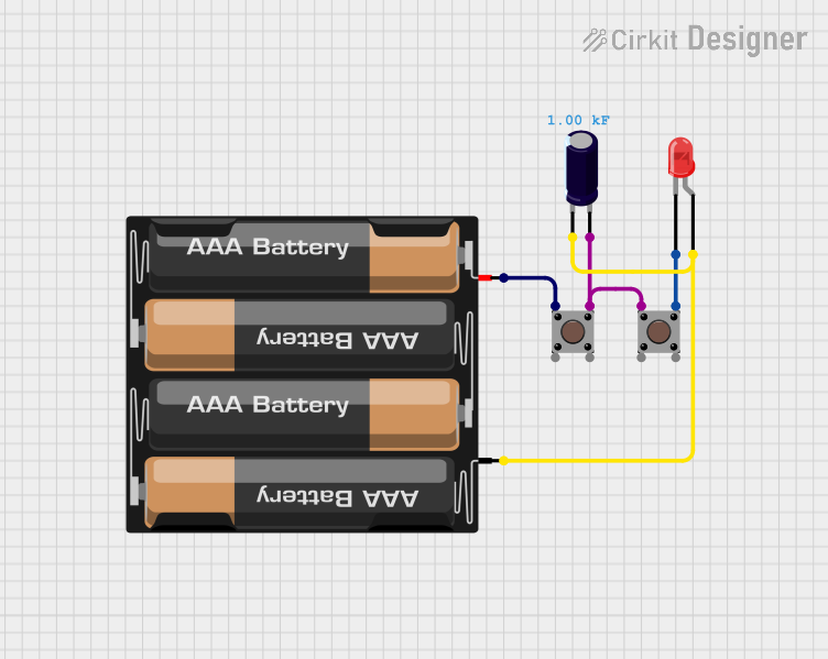
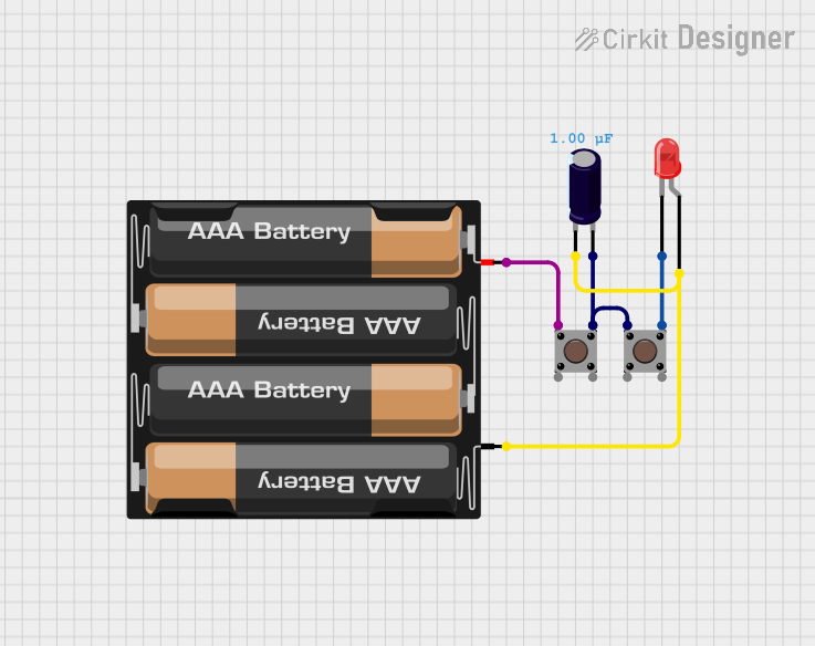
  1. Wiring the Pushbutton:

    • Connect one pin of the pushbutton to the positive voltage source (e.g., 5V).
    • Connect the other pin to the input pin of a microcontroller or the desired circuit.
    • Use a pull-down resistor (typically 10kΩ) between the input pin and ground to ensure a stable low signal when the button is not pressed.
  2. Testing the Pushbutton:

    • When the button is pressed, the circuit is completed, and the input pin will read a HIGH signal.
    • When released, the pull-down resistor ensures the input pin reads a LOW signal.

Example: Connecting to an Arduino UNO

Below is an example of how to use the Red Cap Pushbutton with an Arduino UNO to toggle an LED:

// Define pin numbers
const int buttonPin = 2;  // Pushbutton connected to digital pin 2
const int ledPin = 13;    // LED connected to digital pin 13

// Variable to store button state
int buttonState = 0;

void setup() {
  pinMode(buttonPin, INPUT);  // Set pushbutton pin as input
  pinMode(ledPin, OUTPUT);   // Set LED pin as output
}

void loop() {
  // Read the state of the pushbutton
  buttonState = digitalRead(buttonPin);

  // If the button is pressed, turn on the LED
  if (buttonState == HIGH) {
    digitalWrite(ledPin, HIGH);  // Turn on LED
  } else {
    digitalWrite(ledPin, LOW);   // Turn off LED
  }
}

Important Considerations:

  • Debouncing: Mechanical pushbuttons may produce noise or multiple signals when pressed. Use a software debounce routine or a capacitor across the pins to filter out unwanted signals.
  • Voltage Compatibility: Ensure the operating voltage of the pushbutton matches your circuit requirements.
  • Mounting: Secure the pushbutton properly to avoid accidental disconnections or damage.

Troubleshooting and FAQs

Common Issues:

  1. Button Not Responding:

    • Cause: Loose connections or incorrect wiring.
    • Solution: Double-check the wiring and ensure all connections are secure.
  2. Button Produces Erratic Signals:

    • Cause: Signal bouncing due to mechanical contacts.
    • Solution: Implement a debounce routine in software or use a capacitor (e.g., 0.1µF) across the button terminals.
  3. LED Does Not Turn On in Arduino Example:

    • Cause: Incorrect pin configuration or faulty components.
    • Solution: Verify the pin numbers in the code match your circuit. Test the LED and pushbutton separately to ensure they are functional.

FAQs:

Q: Can I use the Red Cap Pushbutton with a 3.3V microcontroller?
A: Yes, the pushbutton is compatible with 3.3V systems. Ensure the pull-down resistor is appropriately sized for your circuit.

Q: How do I mount the pushbutton on a panel?
A: The pushbutton typically comes with a threaded shaft and a nut. Drill a hole in the panel, insert the pushbutton, and secure it with the nut.

Q: Can the pushbutton handle AC voltage?
A: The Red Cap Pushbutton is designed for low-voltage DC applications. Using it with AC voltage is not recommended unless specified by the manufacturer.

By following this documentation, you can effectively integrate the Red Cap Pushbutton into your projects and troubleshoot any issues that arise.