How to Use Esp32 POE: Examples, Pinouts, and Specs
Introduction
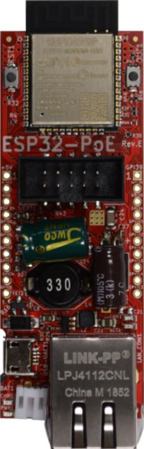
The ESP32-POE-ISO, manufactured by Olimex, is a versatile microcontroller designed for Internet of Things (IoT) applications. It combines the power of the ESP32 chip with built-in Wi-Fi and Bluetooth capabilities, making it ideal for wireless communication. One of its standout features is Power over Ethernet (PoE) support, which allows the device to receive both power and data through a single Ethernet cable. This simplifies installation, reduces wiring complexity, and makes it suitable for applications where power outlets are not readily available.
Explore Projects Built with Esp32 POE


Explore Projects Built with Esp32 POE
Common Applications and Use Cases
- Smart home automation systems
- Industrial IoT monitoring and control
- Remote sensors and data loggers
- Networked devices in offices or factories
- Security and surveillance systems
- Energy management and smart metering
Technical Specifications
The ESP32-POE-ISO is packed with features that make it a robust and reliable choice for IoT projects. Below are its key technical specifications:
General Specifications
| Feature | Description |
|---|---|
| Microcontroller | ESP32 dual-core processor with Xtensa LX6 architecture |
| Clock Speed | Up to 240 MHz |
| Flash Memory | 4 MB |
| RAM | 520 KB SRAM |
| Connectivity | Wi-Fi 802.11 b/g/n, Bluetooth 4.2 (Classic and BLE) |
| Ethernet | 10/100 Mbps Ethernet with PoE support |
| Power Input | PoE (IEEE 802.3af compliant) or 5V via micro-USB |
| Isolation | Built-in galvanic isolation for Ethernet |
| Operating Voltage | 3.3V (logic level) |
| Operating Temperature | -40°C to +85°C |
| Dimensions | 57 x 50 mm |
Pin Configuration and Descriptions
The ESP32-POE-ISO features a variety of pins for interfacing with external components. Below is the pinout and description:
| Pin Name | Pin Number | Description |
|---|---|---|
| VIN | 1 | Power input (5V) when not using PoE |
| GND | 2 | Ground |
| GPIO0 | 3 | General-purpose I/O pin, used for boot mode selection |
| GPIO2 | 4 | General-purpose I/O pin |
| GPIO4 | 5 | General-purpose I/O pin |
| GPIO5 | 6 | General-purpose I/O pin |
| TXD0 | 7 | UART0 Transmit |
| RXD0 | 8 | UART0 Receive |
| SCL | 9 | I2C Clock |
| SDA | 10 | I2C Data |
| EN | 11 | Enable pin, used to reset the ESP32 |
| 3V3 | 12 | 3.3V output for powering external components |
| ETH_TX+ | 13 | Ethernet transmit positive |
| ETH_TX- | 14 | Ethernet transmit negative |
| ETH_RX+ | 15 | Ethernet receive positive |
| ETH_RX- | 16 | Ethernet receive negative |
Usage Instructions
How to Use the ESP32-POE-ISO in a Circuit
Powering the Device:
- Use an Ethernet cable connected to a PoE-enabled switch or injector to power the device and provide network connectivity.
- Alternatively, power the device via the micro-USB port using a 5V power source.
Connecting Peripherals:
- Use the GPIO pins to connect sensors, actuators, or other peripherals.
- For I2C devices, connect to the SDA and SCL pins.
- For UART communication, use the TXD0 and RXD0 pins.
Programming the ESP32:
- Connect the ESP32-POE-ISO to your computer via the micro-USB port.
- Install the necessary drivers for the USB-to-serial converter (if required).
- Use the Arduino IDE or ESP-IDF to write and upload code to the ESP32.
Network Configuration:
- Configure the Wi-Fi or Ethernet settings in your code to connect the ESP32 to your network.
- For PoE, ensure your network switch or injector is IEEE 802.3af compliant.
Important Considerations and Best Practices
- Ensure the Ethernet cable is securely connected to avoid intermittent power or data issues.
- Use a PoE switch or injector that complies with the IEEE 802.3af standard to prevent damage to the device.
- Avoid exceeding the maximum current draw of the 3.3V output pin when powering external components.
- When using Wi-Fi, ensure the antenna has a clear line of sight for optimal signal strength.
- Use proper isolation techniques when interfacing with high-voltage or noisy environments.
Example Code for Arduino IDE
Below is an example of how to connect the ESP32-POE-ISO to a Wi-Fi network and send data to a server:
#include <WiFi.h>

// Replace with your network credentials
const char* ssid = "Your_SSID";
const char* password = "Your_PASSWORD";

void setup() {
  Serial.begin(115200); // Initialize serial communication at 115200 baud
  delay(1000);

  // Connect to Wi-Fi
  Serial.println("Connecting to Wi-Fi...");
  WiFi.begin(ssid, password);

  while (WiFi.status() != WL_CONNECTED) {
    delay(500);
    Serial.print(".");
  }

  Serial.println("\nWi-Fi connected!");
  Serial.print("IP Address: ");
  Serial.println(WiFi.localIP()); // Print the device's IP address
}

void loop() {
  // Add your main code here
}
Troubleshooting and FAQs
Common Issues and Solutions
Device Not Powering On:
- Ensure the Ethernet cable is connected to a PoE-enabled switch or injector.
- Verify the micro-USB cable and power source are functioning correctly.
Wi-Fi Connection Fails:
- Double-check the SSID and password in your code.
- Ensure the Wi-Fi network is within range and not overloaded.
Ethernet Not Working:
- Verify that the Ethernet cable is securely connected.
- Ensure the network switch or injector is IEEE 802.3af compliant.
- Check for proper grounding to avoid electrical noise interference.
Code Upload Fails:
- Ensure the correct COM port is selected in the Arduino IDE.
- Press and hold the "BOOT" button on the ESP32-POE-ISO while uploading the code.
FAQs
Q: Can I use the ESP32-POE-ISO without PoE?
A: Yes, you can power the device via the micro-USB port using a 5V power source.
Q: What is the maximum current output of the 3.3V pin?
A: The 3.3V pin can supply up to 500 mA, but ensure not to exceed this limit to avoid damaging the device.
Q: Is the Ethernet port galvanically isolated?
A: Yes, the ESP32-POE-ISO features built-in galvanic isolation for Ethernet, ensuring safe operation in industrial environments.
Q: Can I use the ESP32-POE-ISO with the Arduino IDE?
A: Yes, the ESP32-POE-ISO is fully compatible with the Arduino IDE. Install the ESP32 board package to get started.
This concludes the documentation for the ESP32-POE-ISO. For further assistance, refer to the official Olimex documentation or community forums.